The fastest path from a master model to low-volume replicas
- The workflow uses a master pattern, a silicone mold, and a liquid polyurethane resin filled under vacuum to reduce trapped air.
- It is strongest when you need cosmetic quality, short lead times, and low-volume production, not long-run economics.
- A single silicone mold often yields about 10 to 25 parts before wear becomes a concern.
- Tooling and first parts are commonly turned around in days, with full projects often landing around 1 to 2 weeks.
- It is not the same as thermoforming or vacuum forming, which start from heated sheet stock.
What this process is really for
I treat this method as a bridge process. A good master model is copied into silicone, the mold is filled with resin under vacuum, and the result is a small batch of parts that looks and feels much closer to final production than a 3D print usually does.
That makes it a strong fit for enclosure checks, visual samples, demo parts, and bridge production while a design is still moving. It is weaker when the part must survive high heat, repeated impact, or very high volumes, because silicone tools wear and polyurethane does not behave exactly like an injection-molded thermoplastic.
In other words, I would use it when speed, appearance, and flexibility matter more than perfect long-run economics. That distinction matters, because the next step is understanding the tooling cycle itself.
How the mold and resin cycle actually works
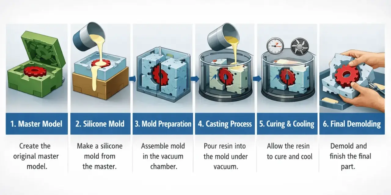
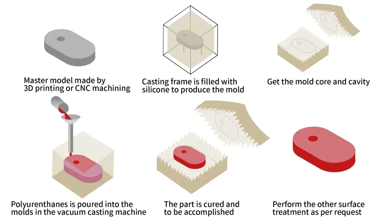
The workflow begins with a stable master pattern, usually made by CNC machining or high-resolution 3D printing. I care a lot about surface quality here, because the silicone copies everything: print lines, tool marks, and even tiny flaws.
1. Build the master pattern
The master is the original shape that the silicone will copy. If the final part needs a polished face, I would finish the master to that standard first, because the mold will reproduce the finish with very little forgiveness.
2. Pour the silicone tool
Liquid silicone is cast around the master to create a split mold. Once cured, the mold is cut open along a planned parting line, which is the seam where the two halves separate.
3. Fill under vacuum
The resin is mixed, degassed, and pulled into the cavity under vacuum. That vacuum step is what helps prevent bubbles in thin sections, sharp corners, and cosmetic surfaces.
Read Also: Overmolding Explained - The Ultimate Guide to Multi-Material Parts
4. Cure, demold, and trim
After curing, the part is removed, gates are trimmed, and the mold goes back to work. In many jobs the master pattern and silicone tool can be ready in a few days, while the full production run often takes about 1 to 2 weeks depending on complexity and cure time.
That cycle explains why silicone tooling is attractive for short runs, but it also shows why it cannot compete with hard tooling on volume. The comparison with thermoforming and injection molding makes that tradeoff much easier to see.
Why it is different from thermoforming and injection molding
I see teams confuse these processes because they all involve molds, and two of them even use the word “vacuum.” The physics are not the same, though. Thermoforming starts with a heated plastic sheet; this casting workflow starts with liquid resin in a silicone cavity.
| Process | Best for | Tooling style | Main tradeoff |
|---|---|---|---|
| Silicone casting replica method | Prototypes, pilot runs, cosmetic samples, short batches | Soft silicone mold made from a master pattern | Limited mold life and lower heat resistance |
| Injection molding | High-volume identical parts | Hard metal tooling | High upfront cost and longer tooling time |
| Thermoforming / vacuum forming | Trays, covers, panels, enclosures, larger sheet-based parts | Forming mold, often aluminum or wood for short runs | One-sided detail and thickness variation in the sheet |
That comparison is the real filter. If the part needs low-cost tooling and only a few dozen copies, the silicone route is often the smart move. If the part needs long-run repeatability, injection molding wins. If the part starts as a sheet and needs broad, shallow geometry, thermoforming is usually the cleaner fit.
The practical lesson is simple: the right process depends less on the name of the part than on its geometry, quantity, and quality target. From there, the next question is where the method actually earns its keep in a project.
Where it earns its keep in real projects
I reach for this process most often when a part needs to be handled, shown, or assembled rather than simply looked at on a screen. It is especially useful when the design team wants a part that behaves like a near-final product without paying for steel tooling too early.
- Appearance prototypes - useful when finish, color, and form need to be approved by stakeholders before a larger investment.
- Fit and assembly checks - useful when housings, clips, bezels, or covers need to confirm tolerance stack-up.
- Sales and demo samples - useful when the part must look credible in front of customers, investors, or distributors.
- Bridge production - useful when a product needs to ship in limited numbers while hard tooling is still in progress.
- Market tests - useful when you want to compare colors, finishes, or small design variants without committing to permanent tooling.
I would not use it as the default answer for a part that needs thousands of copies, strong long-term heat performance, or highly regulated material behavior. That is where the process starts to fight its own limits. Once the use case is clear, the next filter is geometry, because the part itself determines how long the mold survives.
Design choices that make or break the result
Most failures I see are not dramatic. They come from design choices that looked harmless on screen and became expensive in silicone. If I had to narrow it down, I would focus on a few rules that consistently improve the outcome.
- Keep wall thickness as even as possible - sudden changes create sink, warp, and uneven shrinkage.
- Add draft where you can - draft is the slight taper that helps a part release from the mold without tearing the silicone.
- Avoid unnecessary undercuts - every undercut adds mold complexity and shortens tool life.
- Place gates where trimming is acceptable - a gate is the feed channel for resin, and it should not land on the most visible face unless you are willing to clean it up.
- Respect the parting line - the seam where the mold halves meet should be planned, not accidental.
- Finish the master properly - if the master looks rough, the replica will look rough too.
I also warn teams about thin ribs, deep blind pockets, and sharp internal corners. They trap air, create weak spots, and make demolding harder than it should be. A silicone tool is forgiving in one sense, but it still punishes bad geometry.
Material choice and surface expectations are the other half of the decision, and they deserve the same discipline.
Materials, finishes, and what you can realistically expect
One reason I like this method is the range of resin families available. You can simulate rigid housings, slightly flexible clips, soft-touch grips, and even clearer parts for windows or lenses. The important caveat is that these are mimics, not perfect duplicates of every injection-molded polymer.
- Rigid ABS-like resins - good for housings, covers, and general-purpose prototypes where you want a familiar plastic feel.
- PP-like resins - useful when you want more flex and a more forgiving snap-fit behavior.
- PC-like resins - chosen when toughness and clearer parts matter, though scratch resistance still needs review.
- Elastomeric resins - useful for grips, seals, soft bumpers, and parts measured by Shore hardness, which is the scale used to describe softness or stiffness.
- Colored and textured finishes - useful when appearance matters, because the mold can carry texture and the resin can be pigmented or painted after cure.
What I would not expect is perfect equivalence to every thermoplastic label on a spec sheet. An ABS-like resin may look and handle like ABS, but heat resistance, creep, UV stability, and long-term fatigue can still differ. If the part will live in a hot cabin, near electronics, or under sustained load, I would validate that resin carefully before signing off.
Surface finish follows the master closely, which is both a strength and a warning. If the master is polished, the replicas can look excellent. If the master is rough, the replicas will reproduce the roughness just as faithfully. That is why the final check before a run matters more than people usually admit.
What I would verify before I approve a run
Before I green-light a batch, I run through a short checklist. It saves time, and it usually exposes the hidden assumption that would otherwise become a rework order.
- The target quantity fits the realistic mold life, not the optimistic one.
- The resin can handle the expected temperature, handling, and chemical exposure.
- The cosmetic standard is agreed in advance, including visible seam lines and gate marks.
- The tolerance stack-up still works after trim, cure shrinkage, and assembly clearance are considered.
- The master pattern is finished well enough that the mold will copy the right surface, not the wrong one.
- A fallback plan exists if the run has to be repeated or a second colorway is needed.
If the part fits the quantity, finish, and performance window, this is one of the most efficient ways I know to move from concept to credible replicas without waiting on metal tooling. If it does not, I would rather move earlier to injection molding or, for sheet-based parts, thermoforming, than force a process to do a job it was never meant to carry.