3D printing for casting is most useful when I need a fast pattern, a low-cost mold, or a way to test a part before I commit to hard tooling. The real advantage is not the printer itself; it is the speed, geometry freedom, and reduced risk it brings to foundry work, thermoforming, and low-volume molding. In practice, that means fewer weeks spent waiting on machined tooling and fewer expensive mistakes on the first trial.
The essentials before you commit to a casting workflow
- Direct investment casting is the shortest route from digital model to metal when the part is small, detailed, and low volume.
- Indirect investment casting adds a wax step, but it can make repeatable short runs easier to manage.
- Sand casting keeps tooling costs low, but finish and dimensional accuracy are weaker than with investment casting.
- Thermoforming and vacuum forming benefit from printed bucks and molds when you need shallow plastic parts, packaging, or custom shells.
- SLA-style resin systems are usually the safest starting point when surface finish, heat resistance, and detail all matter.
Which workflow fits your part best
I start with the end material, not the printer. That sounds obvious, but it prevents a lot of expensive wrong turns. A printed pattern for metal casting solves a different problem than a printed mold for thermoforming, and a printed master for silicone molding sits somewhere in between.
| Workflow | Best fit | Why I use it | What to watch |
|---|---|---|---|
| Direct investment casting | Intricate metal parts, jewelry, small brackets, short runs | Fastest path from CAD to metal with strong design freedom | Burnout quality, surface cleanup, and support marks matter a lot |
| Indirect investment casting | Repeat wax patterns from a printed master tool | Useful when you want repeatability without machining a metal wax mold | One extra process step and shrinkage compensation are still required |
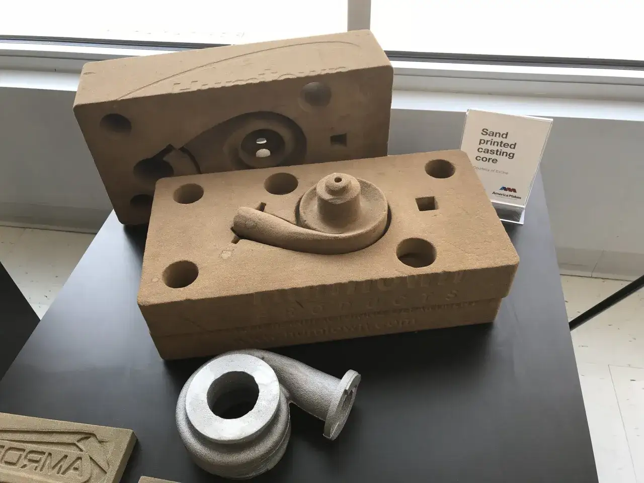
| Sand casting | Larger parts, rough prototypes, one-off to medium volume work | Low tooling cost and fast pattern iteration | Surface finish and accuracy are weaker than with investment casting |
| Printed thermoforming mold | Shallow plastic shells, packaging, custom covers, prototype housings | Fast, inexpensive, and easy to revise before committing to metal tooling | Heat resistance, draft, and draw depth define whether it will succeed |
That table is the filter I use before I touch CAD. Once the route is clear, the workflow itself becomes much easier to control, so the next step is to break the process down from design to finished part.
How I break the process down from CAD to cast part
The cleanest projects follow the same logic: design for the process, print the tool, finish it properly, then cast or form with one controlled test cycle before scaling up. Skipping any of those steps usually shows up later as a scrap problem, not a nice surprise.
- Start with the final material and volume. Metal, silicone, urethane, and thermoplastic sheets all punish different mistakes.
- Build the CAD around the process. I add shrinkage allowance, draft, venting, gate locations, and parting lines before I think about print orientation.
- Print the pattern, mold, or master in the right material. The geometry is only half the story; the print has to survive heat, pressure, or burnout.
- Wash, post-cure, and finish the surface. A rough or under-cured tool gives you a rough or unstable part.
- Run one test pour or test form. I want to see where the part sticks, where it wrinkles, and where the air or resin gets trapped.
- Adjust before production. A small change in draft, wall thickness, or support placement is usually cheaper than reprinting the whole tool.
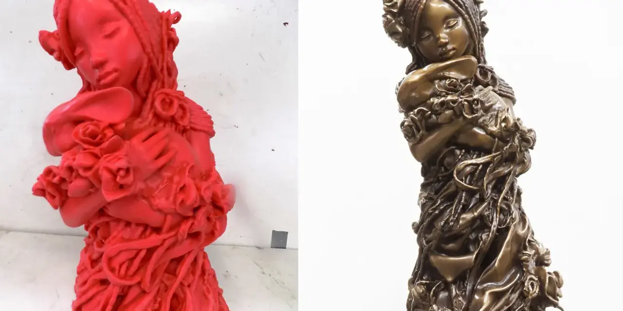
For cast metal, the detail that beginners miss most often is that the printed part is not the final answer. It is a bridge to the final geometry, and bridge parts need to be designed like tooling, not like display models. That is why material choice matters so much in the next phase.
What printer and material choices actually matter
I treat material selection as a heat and surface-quality problem. If the wrong resin or filament softens, distorts, or leaves residue, the rest of the workflow starts fighting physics instead of helping you make parts.
- Castable resins are the default choice for direct investment casting patterns when I need detail and a cleaner burnout path.
- High-temperature resins are the better fit for molds, wax injection tools, and thermoforming bucks because they hold shape under heat better than standard resins.
- Rigid engineering resins are useful when I want a short-run mold or master with a more stable surface than an ordinary prototype material.
- FDM thermoplastics can work for large bucks or fixtures, but the layer lines usually mean extra sanding, filling, or machining before I trust the surface.
My practical rule is simple. If the surface will define the finished part, print quality has to be treated like tooling quality. That leads straight into the design rules that save most jobs from failure.
Design rules that make the difference between a clean cast and a messy one
Most failures are not caused by the printer. They come from designs that ignore how molten metal, hot plastic, or burnout heat actually behaves. I split the rules into casting patterns and thermoforming molds because the problems overlap, but they are not identical.
Casting patterns
- Compensate for shrinkage in CAD. Do not guess. Use the shrinkage data from the material and casting supplier.
- Keep supports off critical surfaces. Support scars on a show face become expensive to remove later.
- Reduce trapped resin. Hollow large shapes and add drains or vents so you are not burning out unnecessary mass.
- Build gates and vents into the model. I prefer to place flow paths intentionally instead of cutting them in as an afterthought.
- Post-cure thoroughly. Half-cured resin is a common cause of pitting, residue, and unhappy investment shells.
Read Also: Compression Molding - Is It Right For Your Part?
Thermoforming molds
- Use draft liberally. I aim for 4 to 5 degrees on male molds and about 1.5 to 3 degrees on female molds.
- Respect draw ratio limits. A 3:1 draw ratio is generally the upper edge for most vacuum forming work.
- Add vent holes where the sheet must pull into pockets. Without them, the plastic tends to bridge instead of conform.
- Round corners and break sharp edges. Radii reduce webbing, tearing, and stress concentration in the finished part.
- Keep the geometry as shallow as the design allows. Deep draws demand thicker sheet and increase wall-thickness variation.
Those rules are not glamorous, but they are what keep a printed tool from becoming a pretty failure. Once the geometry is under control, the next question is where thermoforming and molding sit alongside casting in a plastics workflow.
Where thermoforming and molding overlap with casting workflows
This is where the plastics side of the story becomes valuable. A printed master can become a silicone mold for urethane or epoxy parts, a printed buck can shape a thermoformed shell, and a printed pattern can seed a casting process when the final part is metal. The common thread is that I am using additive manufacturing to buy speed and flexibility before I spend money on permanent tooling.
In a plastics shop, I like this approach for packaging prototypes, appliance panels, custom covers, light housings, and small production runs of shaped shells. It is especially useful when the part needs a physical fit check before the final tool is worth cutting. I can prove the geometry with a printed mold, then decide whether the next step should be a short-run bridge tool or a fully machined production tool.
The important distinction is cycle life. Printed thermoforming tools are excellent for prototypes, pilot production, and low-volume runs, but they are not a free substitute for aluminum when the part count climbs. The same is true for printed casting patterns: they are a fast route to first articles, not an excuse to ignore downstream process control.
Once you see that boundary clearly, the common failure modes become easier to predict instead of mysterious.
The failure modes I watch for first
When a printed tool fails, the symptom is usually obvious and the cause is usually boring. I keep a short checklist for the problems I see most often.
| Symptom | What it usually means | What I do |
|---|---|---|
| Pitting or ash in the cast surface | The print was under-cured, trapped resin was left in the model, or burnout was too aggressive for the resin | Wash more thoroughly, post-cure fully, and reduce trapped material in the pattern |
| Warped mold or softened face | The material is not stable enough for the heat load | Switch to a higher-temperature resin or redesign the tool with less thermal stress |
| Webbing or thinning in a thermoformed part | Sharp corners, too much draw depth, or insufficient venting | Add radii, reduce depth, and revise the vent layout |
| Part sticks to the mold | Not enough draft or poor surface prep | Add draft, polish or texture intentionally, and use release only when the process allows it |
| Cracked investment shell | Too much internal mass, poor drainage, or a weak burnout path | Hollow the part, improve drains and vents, and follow a resin-specific burnout schedule |
If I had to reduce the whole subject to one rule, it would be this: do not expect a printed tool to behave like machined aluminum unless you have already tested the heat, pressure, and finish conditions that matter. That is why the final decision should be practical, not aspirational.
A practical way to choose the right path in a US prototype shop
In a typical US prototype shop, I would sequence the work like this: print a pattern first if the end part is metal; print a thermoforming mold first if the end part is plastic; and only move to machined tooling after the geometry and demand have stopped changing. That order keeps cost low while still giving you real process data.
- Use direct investment casting when the part is metal, detailed, and low volume.
- Use indirect investment casting when you need repeated wax patterns and want to separate the master tool from the final burnout stage.
- Use sand casting when budget matters more than finish and the part can tolerate more cleanup.
- Use thermoforming or vacuum forming when the final part is a plastic shell, cover, tray, or packaging form that benefits from fast tool iteration.
- Move to hard tooling when the cycle count, finish target, or dimensional stability makes printed tools uneconomical.
That is the balance I would recommend for Ermax-design.com readers: use additive manufacturing to learn fast, not to skip process discipline. If I were building this from scratch today, I would start with an SLA-based pattern for casting and a high-temp printed mold for thermoforming, then qualify both on one or two parts before scaling the workflow further.