Advanced 3D printing is no longer just about making complex shapes. In 2026, the real question is whether a printed part can hold tolerance, survive loading, finish cleanly, and still make economic sense in a real workflow. This article breaks down the processes, design rules, post-processing steps, and application choices that separate a useful production tool from a nice demo piece.
The practical points that matter before you choose a process
- Process choice comes first. SLA, SLS/MJF, FDM, PolyJet, and metal systems solve different problems, so start from function, not machine hype.
- Geometry drives success. Wall thickness, orientation, supports, and clearances often matter more than nominal layer height.
- Post-processing is part of manufacturing. Washing, depowdering, smoothing, coating, machining, and inspection can decide whether a part is production-ready.
- Functional parts need validation. A single good sample does not prove repeatability across a batch or across different build positions.
- The best ROI is usually practical. Jigs, fixtures, enclosures, service parts, and low-volume production often benefit more than display-only models.
What advanced 3D printing actually means in 2026
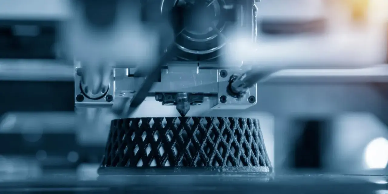
For me, the shift is simple: additive manufacturing is moving from prototype support into production support. Teams now use it for jigs, fixtures, service parts, patient-specific devices, lightweight housings, and end-use components when the geometry justifies it. The best systems compete on repeatability, material behavior, workflow control, and finishing, not on layer count alone.
The mistake I still see is treating resolution as the main metric. A printer can have fine layers and still deliver poor fit if the material shrinks, the part is oriented badly, or post-processing is inconsistent. That is why ISO/ASTM terminology, proper tolerancing, and a realistic process chain matter more than a marketing spec sheet. Once you look at the full chain, the next step is choosing the right process for the job.
The main processes I compare first
I do not start with the machine brand. I start with the part’s job: surface quality, strength, batch size, temperature resistance, and how much labor the finish will need. That usually narrows the field fast.
| Process | Best for | Main strengths | Main tradeoffs |
|---|---|---|---|
| SLA or DLP | Fine detail, smooth surfaces, clear parts, master models | Excellent feature resolution, clean cosmetic output, strong fit for small precision parts | Supports can leave marks, resin parts can shrink after curing, material choice is narrower than nylon systems |
| SLS | Functional nylon parts, clips, housings, internal channels, complex assemblies | No dedicated supports, strong functional parts, good for nested or hollow geometry | Rougher surface, powder removal is required, finish often needs post-processing |
| MJF | Production-oriented nylon parts, short runs, repeatable batches | Strong throughput, consistent results, good batch economics for repeated parts | Surface finish still needs work for cosmetic products, thermal control matters a lot |
| Material extrusion or FDM | Large fixtures, concept parts, engineering thermoplastics, low-cost iteration | Low entry cost, broad material availability, easy internal adoption | Layer lines are visible, anisotropy is real, supports and warping can hurt accuracy |
| PolyJet | Full-color models, multi-material concepts, presentation parts | Very fine surfaces, realistic visual mockups, multi-material flexibility | Not my first choice for high-heat or long-life structural parts |
| Metal LPBF | High-strength metal parts, lightweight structures, conformal cooling features | Complex metal geometry, high performance, strong consolidation potential | Qualification, support removal, and downstream inspection add cost and time |
As a planning baseline, vendor examples commonly run around 100 microns for SLA, 110 microns for SLS, and 120 microns for FDM. Dimensional accuracy is a separate issue: resin systems often land in the ±0.15% to ±0.3% range depending on feature size, SLS and MJF commonly sit around ±0.5% or 0.3 mm, and FDM is usually looser at about ±0.5% with a 0.5 mm floor. I use those numbers as a starting point, then verify them against the actual geometry and post-processing plan.
That comparison is useful, but it still leaves the most important question unanswered: how should the part itself be designed so the process works in your favor?
Designing for the part, not the printer
The best prints usually come from parts that were designed for the process, not adapted to it later. I think in terms of wall behavior, fit, orientation, and how the part will be cleaned or assembled after printing. That is the real design work, and it is where many projects either save money or quietly burn it.
Wall thickness and orientation
Thin walls are one of the fastest ways to create false confidence. On current resin platforms, 0.2 mm supported walls are possible, but that is not the same thing as a comfortable production target for loaded features. In FDM, a common rule is 0.3 mm in the XY plane and 0.5 mm in Z, while practical SLS walls usually need about 0.8 mm for usable rigidity. When a wall is load-bearing, I increase the margin rather than trusting the bare minimum.
Orientation matters just as much. A part can look perfect in CAD and still fail because the load runs across weak layer lines, supports land on critical faces, or a long flat section warps during cool-down. If the force path is wrong, the print may be accurate and still not be fit for service.
Clearances, fits, and moving assemblies
Clearance is where additive parts feel either clever or frustrating. For small thin assemblies, a 0.2 mm gap is often enough. For larger, chunkier parts, 0.4 mm is safer. If a design includes moving interfaces, I usually test the tolerance in a small coupon before I commit to the full assembly.
Threads deserve special caution. Once you get below M6, print tolerances start to eat into usable fit very quickly, so inserts or secondary machining are often the smarter choice. The same is true for snap-fits and living hinges: they can work well in nylon, but a resin that looks strong on screen may fail in the first flex cycle.
Hollowing, lattices, and topology optimization
Hollowing is useful, but it is not free. In resin parts, you need vent and drain holes, or you risk trapped material, pressure issues, and messy cleanup. In powder-bed polymer parts, you need to think about powder escape paths instead.
Lattice structures and topology optimization are where additive manufacturing starts to feel different from conventional fabrication. You can remove material from low-stress zones and keep stiffness where it matters. I reach for this approach in lightweight housings, ergonomic grips, drone components, and tooling that needs strength without unnecessary mass.Read Also: 3D Printed Blast Gates - Build Better for Your Workshop
Supports and self-supporting geometry
Supports are not just a cleanup step. They are a design decision that affects surface finish, dimensional stability, and labor. I try to keep support marks away from sealing faces, mating faces, and cosmetic surfaces. When the geometry allows it, self-supporting angles are worth the effort because they reduce downstream work.
In powder-bed polymer systems, the equivalent risk is trapped powder and inaccessible cavities. That is why I pay attention to internal channels, drain paths, and geometry that can actually be cleared after the build. Once the part is structurally sound, the next battle is finishing and inspection.
Post-processing is where production value shows up
This is the stage that decides whether the part is merely printed or genuinely usable. I have seen more projects lose time in finishing than in the actual build, which is why I treat post-processing as part of manufacturing, not as an optional afterthought.
- SLA and DLP usually need washing, support removal, and post-curing. Post-curing can change dimensions, so compensation matters.
- SLS and MJF typically need depowdering and media blasting. In some automated workflows, hands-on cleaning can drop to about 15 minutes.
- Vapor smoothing can seal surfaces and improve appearance, including around complex internal geometry, but it adds cost and is not right for every polymer.
- Dyeing, painting, and coating help functional parts look finished and can improve resistance to UV, corrosion, or handling wear.
- CNC machining and inserts are often the smartest way to finish critical holes, threads, and sealing faces.
- Inspection and testing are essential when the part must fit, seal, or carry load repeatedly.
My rule is blunt: if the part must look or perform like a manufactured component, finish planning starts before the first layer is printed. If you leave it until the end, you often discover that the expensive part is not the print, it is the cleanup.
Once finishing is under control, the next question is where these methods create the biggest business return.
Where the biggest returns usually come from
The most valuable parts are often the boring ones that keep production moving. That is why I keep coming back to fixtures, jigs, and low-volume functional parts. They are not glamorous, but they are often the fastest way to recover time and tooling cost.
| Application | Best-fit process | Why it works | What to watch |
|---|---|---|---|
| Jigs and fixtures | FDM, SLS, MJF | Fast turnaround, low tooling cost, easy iteration | Heat resistance, clamp load, wear surfaces |
| End-of-arm tooling | SLS, MJF, reinforced FDM | Lightweight parts reduce robot load and speed up replacement | Creep, grip wear, dimensional stability |
| Functional prototypes | SLA for detail, SLS or MJF for fit and function | You can test geometry, assembly, and usability before committing to tooling | Do not validate only appearance; test the actual loads |
| Custom enclosures and ducting | SLS, MJF, FDM | Internal channels and odd shapes are easier than with subtractive methods | Wall thickness, sealing, and heat management |
| Medical and dental models | SLA, validated resin workflows, metal LPBF where appropriate | Fine detail and repeatability matter more than raw speed | Documentation, regulatory path, material validation |
| Lightweight structural parts | SLS, MJF, metal LPBF | Lattices and consolidation can cut weight without sacrificing performance | Qualification and repeatability at scale |
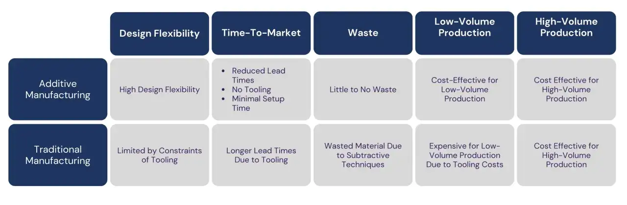
What makes these applications pay off is not novelty. It is the combination of lower tooling cost, shorter lead time, and geometry that conventional methods struggle to produce. In U.S. manufacturing teams, that often means digital inventory, spare parts, and local production instead of waiting on a mold or on overseas tooling.
That leads directly into the decision that matters most for budget: which process should actually get the job.
How to choose a process without overspending
I make the choice from function backward. If the part needs cosmetic detail, I start with resin. If it needs durable nylon behavior and internal complexity, I start with SLS or MJF. If the goal is cheap iteration or a large fixture, I start with FDM. If the part must handle high heat or heavy structural load, I move into metal only after the design and quality plan are clear.
| Your priority | Start here | Why |
|---|---|---|
| Cosmetic surface and fine detail | SLA or DLP | Best surface finish and sharpest small features |
| Durable nylon part with complex geometry | SLS or MJF | Strong functional parts without dedicated supports |
| Low-cost concept work or large fixtures | FDM | Cheap entry and broad material availability |
| Multi-material or full-color realism | PolyJet | Useful for presentation and design validation |
| Heat, load, or metal performance | Metal LPBF | Best fit when plastic is no longer enough |
| Unproven demand or no in-house capacity | Service bureau first | Lower risk while you validate part demand and process choice |
Cost is not just machine price. The real drivers are material cost, build time, orientation, supports, powder removal, finishing labor, inspection, and scrap. A part that prints in four hours can still take a full day once finishing and checking are included, and that is where budgets often get surprised.
For teams building a serious supply chain, I also care about terminology and drawing discipline. ISO/ASTM 52900 keeps process language consistent, and standard tolerancing practice helps every supplier measure the same thing instead of arguing about what “close enough” means. If the part will enter production, that paperwork is not overhead, it is control.
The validation checklist I would run before scaling a part family
When a part moves from one-off success to repeated production, I want proof, not optimism. My validation checklist is short, but I use it ruthlessly because it catches the failures that matter.
- Print the worst-case geometry first, not just the prettiest one.
- Use the final material and the final post-processing sequence, not a shortcut version.
- Measure multiple parts from different locations in the build, not a single sample.
- Check fit after heat, vibration, humidity, or chemical exposure if the part will see those conditions.
- Lock orientation, nesting, support strategy, and inspection criteria before volume ramps up.
- Document which surfaces are cosmetic, which are functional, and which can tolerate secondary machining.
That is the difference between a clever prototype and a dependable manufacturing tool. When geometry, material, finishing, and inspection stay under control, additive stops being a special case and becomes part of the standard playbook. That is where the real value of modern 3D printing shows up.