The practical answer to what is an FDM printer is simple: it is a machine that turns a plastic filament into a solid part by heating it and laying it down layer by layer. I find this process especially useful when the goal is a real, functional plastic part rather than a purely visual model, because FDM sits in a useful middle ground between speed, cost, and material choice. In this article, I break down how the process works, which materials matter most, where the technology excels, and where it still has clear limits.
The essential facts about FDM printing
- An FDM printer builds parts by extruding melted thermoplastic through a heated nozzle.
- The process is popular because it is relatively low cost, easy to learn, and suitable for functional plastic parts.
- Common materials include PLA, PETG, ABS, TPU, nylon, and composite filaments.
- Layer lines, support removal, and Z-axis weakness are the main trade-offs to expect.
- FDM is usually the best fit for prototypes, jigs, fixtures, enclosures, and utility parts.
What an FDM printer actually does
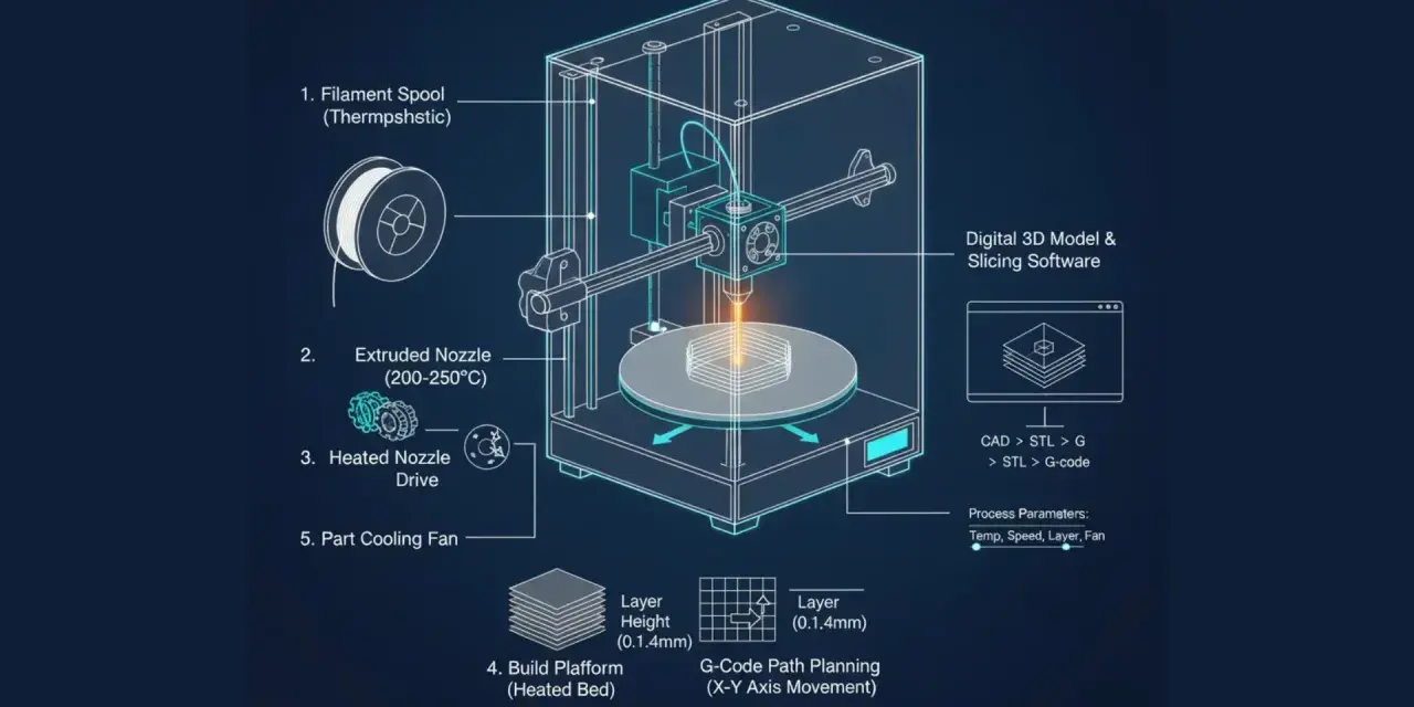
FDM stands for fused deposition modeling, and the idea is straightforward once you strip away the jargon. A spool of thermoplastic filament feeds into an extruder, the material is heated until it softens, and the nozzle deposits it in a controlled path on the build plate. The printer repeats that motion hundreds or thousands of times, stacking thin cross-sections until the 3D model becomes a physical object.
In daily use, I think of the machine as three systems working together: the motion system that positions the nozzle, the hot end that melts the plastic, and the slicer software that converts the digital model into toolpaths. The slicer matters more than most beginners expect because it decides layer height, wall thickness, support strategy, infill, and print speed. That is why two parts printed on the same machine can look and perform very differently.
One practical detail is the naming. Many desktop brands and software tools say FFF, or fused filament fabrication, while industrial equipment and much of the broader market still say FDM. For most users, the workflow is the same enough that the distinction matters less than the part quality you actually get. Once that basic mechanism is clear, the next step is understanding how a model turns into a finished print.
How the workflow turns a model into a part
FDM is easy to understand conceptually, but the process has a few stages that directly affect the final result. Miss one of them, and the print quality usually shows it.
- Design or import the part in CAD or a 3D model file.
- Export it as a printable format such as STL or 3MF.
- Slice the model into layers and generate toolpaths.
- Set the print profile for material, nozzle, supports, and infill.
- Print the part and let it cool before removal.
- Clean up supports, trim strings, and do any sanding or assembly.
Layer height is one of the easiest settings to interpret. A common starting range on desktop machines is roughly 0.1 to 0.3 mm. Thinner layers improve surface finish and detail, while thicker layers print faster and can be perfectly acceptable for brackets, enclosures, and other utility parts. A 0.4 mm nozzle is still the most common general-purpose choice because it balances detail, speed, and material flow well.
Post-processing is not optional if you care about finish. Even a good FDM print can show witness lines, support marks, or slight edge cleanup. I usually tell teams to design with that in mind rather than treating cleanup as an afterthought. That workflow also explains why filament choice matters so much, which is where material behavior comes in.
Which materials work best and why
The biggest advantage of FDM is material flexibility. You are not locked into one generic plastic, and the part can be tuned for appearance, toughness, flexibility, or heat resistance. In practice, standard filament pricing often lands around $20 to $50 per kilogram in the U.S., while engineering-grade blends can cost considerably more.| Material | What it does well | Main trade-off | Common uses |
|---|---|---|---|
| PLA | Easy printing, low warping, clean surface finish | Lower heat resistance and lower toughness than some alternatives | Concept models, fit checks, visual prototypes |
| PETG | Good balance of strength, chemical resistance, and printability | Can string and needs tuning for cleaner surfaces | Enclosures, brackets, functional prototypes |
| ABS | Better heat resistance and impact performance than PLA | More prone to warping and often benefits from an enclosure | Housings, fixtures, tougher utility parts |
| TPU | Flexible, durable, and impact resistant | Slower printing and more finicky feeding | Gaskets, bumpers, grips, vibration-damping parts |
| Nylon | Strong, wear resistant, and useful for loaded parts | Moisture sensitive and often harder to print cleanly | Gears, wear components, functional mechanical parts |
| Carbon-fiber or glass-filled blends | High stiffness and better dimensional stability | Abrasive on nozzles and usually less forgiving to print | Jigs, fixtures, structural parts, lightweight components |
For plastic design work, I care less about the label on the spool and more about the behavior of the finished part. A part that needs to flex repeatedly is a very different problem from a part that must hold a screw boss, survive heat, or resist wear. Material choice sets the ceiling, but real-world success depends just as much on the parts FDM handles well or badly.
Where FDM shines and where it falls short
FDM is at its best when you want a durable plastic part quickly, at relatively low cost, and with enough dimensional control to test a design or use it in service. That is why I see it constantly in prototyping, manufacturing aids, ducting, tool holders, enclosures, and low-volume end-use parts. It is also a strong choice when the part is large, because scaling up an FDM machine is usually more practical than moving to a higher-resolution process for the same size envelope.
The limitations are just as important. FDM parts usually show layer lines, and those layers create anisotropy, which means the part is typically stronger within the layer plane than across the layers. Surfaces with steep overhangs may need supports, sharp features can soften, and tall slender parts can wobble or fail if the setup is not stable. If you need a glossy, cosmetic finish straight off the printer, FDM is usually not the easiest path.
- Best for parts that need to be functional, not flawless.
- Best for thicker geometry, brackets, and mechanically sensible shapes.
- Weakest when the design depends on tiny detail, mirror-like surfaces, or very fine text.
- Needs more care when the part must seal perfectly, resist heat, or carry load across the layer lines.
I also see beginners make the same mistake again and again: they choose infill first and geometry second. In reality, wall count, part orientation, and load path usually matter more than simply filling the inside of the model. That trade-off becomes clearer when you compare FDM with resin and powder-based printing.
How FDM compares with SLA and SLS
If you are deciding between 3D printing technologies, FDM is rarely the absolute best at everything. It is the most balanced choice for many plastic parts, but the other major processes do specific things better.
| Technology | Surface finish | Strength profile | Cost profile | Best fit |
|---|---|---|---|---|
| FDM | Visible layer lines | Good overall, but directionally weaker between layers | Lowest material cost in many cases | Functional prototypes, jigs, fixtures, utility parts |
| SLA | Smoother and finer detail | Good detail, but resin parts can be more brittle | Resin and post-processing are usually costlier | Cosmetic models, small precise parts, detailed surfaces |
| SLS | Powdery surface, less refined visually | Strong and fairly uniform, with no support structures | Generally higher equipment and service cost | Production parts, complex geometry, strong nylon components |
My rule of thumb is simple. If the part needs to look polished right away, SLA usually wins. If the part needs strong, complicated geometry without supports, SLS becomes attractive. If the priority is a practical plastic part at a sensible cost, FDM is often the most efficient answer. Those comparisons matter less than the settings you actually choose, so I move to the practical setup rules next.
Settings that make the biggest difference in real prints
When people ask me how to get better FDM results, I usually start with a small list of high-impact choices instead of throwing every slicer setting at them. Most of the quality gain comes from a few decisions made before the printer even starts moving.
- Use a layer height around 0.2 mm for a dependable general-purpose profile.
- Increase wall count before you obsess over infill, especially for functional parts.
- Orient the model so the main load does not pull layers apart.
- Use supports only where they are needed, because unnecessary supports add cleanup and risk marks.
- Start with moderate speeds, then increase them only after the first successful print.
- Keep filament dry, especially for nylon and TPU, because moisture ruins consistency fast.
If I had to pick one rule, it would be this: orient the part for strength first, appearance second. That usually produces better results than chasing extreme infill or very fine layers. For many plastic parts, 2 to 4 perimeters and 15 to 30 percent infill are a sensible starting point, but I would never treat those numbers as universal. The right profile depends on the part geometry, the machine, and the material.
For ABS and nylon, an enclosure often helps because it stabilizes the build environment and reduces warping. For PLA, the setup is usually easier, which is part of why it remains such a common entry material. If you keep those rules in mind, FDM becomes a very predictable tool instead of a frustrating one.
The practical decision rule I use for plastic parts
When I decide whether to use FDM, I ask three questions. First, does the part need to be functional rather than merely decorative? Second, will the geometry tolerate visible layer lines and some post-processing? Third, can the material handle the heat, load, and environment the part will face? If the answer is yes to most of those, FDM is usually a strong choice.
That is why FDM still matters so much in plastic design and fabrication. It gives designers and engineers a fast way to move from CAD to a real object, and that makes it valuable long before production ever starts. If you understand the workflow, respect the material limits, and design around the process instead of against it, FDM becomes less of a compromise and more of a practical manufacturing method for everyday plastic parts.