In practice, vacuum forming is one of the fastest ways to turn a flat thermoplastic sheet into a usable part, especially when you need a clean outer surface, moderate detail, and sensible tooling cost. I am focusing here on how the process really works, where it fits inside thermoforming and molding, which materials behave best, and what design choices keep parts from warping, thinning, or coming off the tool badly.
What matters most before you choose it
- This is a sheet-forming method, so it works best when one side of the part matters more than the other.
- The process is fast and tool-friendly, but it rewards simple geometry, generous radii, and proper draft.
- Wall thickness changes as the sheet stretches, so deep draws need careful planning.
- HIPS, ABS, PETG, acrylic, and polycarbonate each solve a different problem, and none of them is universal.
- Pressure forming or injection molding is often the better choice when detail, texture, or tolerance demands get tight.
How the process actually works
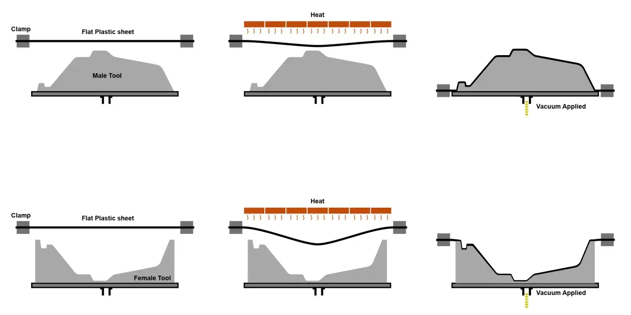
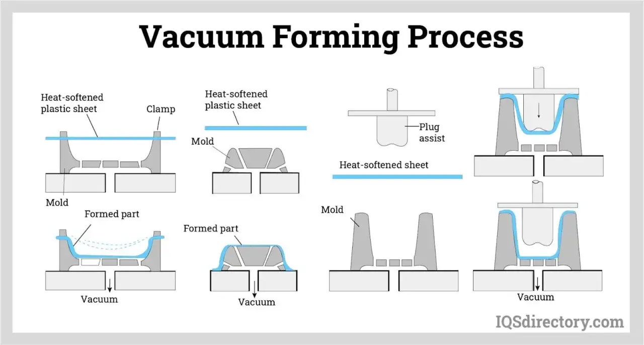
I like to explain sheet forming as controlled stretching. A plastic sheet is clamped, heated until it softens, then pulled over a mold while air is removed from the gap between the sheet and the tool. The sheet cools in place, hardens, and is trimmed into the final part.
The important detail is that the sheet is not being forced into shape with the same kind of pressure you get in closed-cavity molding. When vacuum alone does the work, the forming force is limited by atmospheric pressure, about 14.7 psi. That is enough for many shells, covers, trays, and panels, but it also explains why very sharp detail and deep undercuts are hard to hold.
There are two mold styles I watch closely:
- Male molds shape the inside of the part. They are useful when the inside dimensions matter more than the outside surface.
- Female molds shape the outside of the part. They usually give better cosmetic control on the visible face.
Once you think in those terms, the rest of the process becomes easier to judge. The sheet is not simply copied into the tool; it stretches across it, and that stretch is what drives the thickness pattern. That leads directly into where this method sits inside the larger thermoforming family.
Where it sits inside thermoforming and molding
This process is one branch of thermoforming, which is the broader family of heat-based sheet shaping methods. I do not treat it as a competing category to thermoforming; it is part of thermoforming. What matters is whether the part needs vacuum pull alone, added air pressure, a second sheet, or a completely different molding route.
| Process | Best for | Main strength | Main limitation |
|---|---|---|---|
| Vacuum-assisted sheet forming | Large shells, trays, covers, liners, prototype runs | Simple tooling and quick turnaround | Limited detail and uneven wall thickness on deep draws |
| Pressure forming | Textured panels, cosmetic parts, sharper features | Better detail and surface definition | Higher equipment and tooling complexity |
| Twin-sheet forming | Hollow parts and enclosed structures | Creates a stronger, enclosed form | More complex setup and tooling |
| Injection molding | High-volume parts with tight repeatability | Best dimensional control and feature detail | Highest tooling cost and the slowest launch path |
This is why I do not compare sheet forming and injection molding as if they solve the same problem in the same way. They do not. One is a fast, flexible sheet process; the other is a closed-mold route built for precision and scale. If the part only needs one highly controlled surface, the sheet route often makes more sense than people expect.
The materials that form cleanly and the ones that fight you
Material choice is where good projects separate from frustrating ones. In sheet forming, the plastic is not just a commodity input; it is the thing that decides clarity, impact resistance, release behavior, trim quality, and how much the part will thin as it stretches.
| Material | Why it works | What to watch | Typical use |
|---|---|---|---|
| HIPS | Low cost and easy to form | Lower impact and heat resistance than stronger engineering sheets | Displays, packaging, disposable or short-life parts |
| ABS | Good balance of formability and impact performance | Cosmetic quality depends on heating and cooling control | Enclosures, panels, equipment covers |
| PETG | Forms easily and often gives a clean visual result | Surface can scratch if handling is sloppy | Clear covers, display parts, protective packaging |
| Acrylic | Excellent clarity and a polished look | More brittle than PETG and less forgiving in deep draws | Displays, lenses, visual components |
| Polycarbonate | Very strong and impact resistant | More demanding to form and finish well | Protective guards, safety covers, high-stress parts |
| PP and HDPE | Useful when chemical resistance or toughness matters | Less dimensionally stable, so tolerances usually need to be wider | Industrial parts, liners, utility components |
For planning, I usually separate sheet work into thin-gauge and heavy-gauge territory. Thin-gauge material is under about 3 mm, while heavy-gauge sheet is often around 1.5 to 9.5 mm. That range is not a law of physics, but it is a useful way to think about how much stretch, stiffness, and trimming complexity you are dealing with.
One practical rule I keep coming back to is this: if the part must look clear, choose clarity first and then work backward through impact, heat, and cost. If the part is structural, choose performance first and let appearance follow. That ordering saves a lot of trial-and-error.
Design rules that keep parts from thinning out
This is the section that saves money. Most forming problems are not caused by the machine; they come from a part that asked the sheet to do more than it can do cleanly. The deeper the draw, the more the material stretches, and the more the wall thins in the areas that matter most.
Start with draft and radii, not sharp corners
I usually start with at least 1.5 to 2 degrees of draft on female features and 3 to 5 degrees on male features, then increase it whenever the part is deep or textured. The point is not to chase a perfect number; the point is to make release easy enough that the part does not tear, stick, or scuff on the way out.
Large radii matter just as much. A safe working habit is to keep inside radii at least around the sheet thickness, and larger when the draw is deep. Sharp corners do not just look aggressive on paper. They concentrate stress and pull thickness away from the exact places that often need strength.
Expect thickness variation and design around it
Wall thickness is rarely uniform. In real production, formed dimensions can be held reasonably well, but the material itself will not stay identical from point to point once it stretches over the tool. A common planning mindset is to specify minimum wall where strength matters, not a single nominal wall that assumes the sheet will behave like a machined block.
That is also why draw ratio matters. The more surface area the sheet has to cover compared with the footprint of the part, the more stretch you are asking for. I have seen teams underestimate that early and then spend time trying to “fix” a geometry problem with heat settings. Heat helps, but geometry usually decides the outcome.
Read Also: Thermoforming vs. Molding - Choose the Right Plastic Process
Venting, undercuts, and trim strategy are not afterthoughts
- Venting helps trapped air escape from corners and pockets so the sheet can actually reach the tool surface.
- Undercuts make release harder and often force a redesign or a secondary operation.
- Trim allowance needs to be planned early, because the trimmed edge is part of the part, not a cleanup detail added at the end.
- Tool access matters if the trim will be CNC-routed, die-cut, or saw-cut later.
When these details are ignored, the failures are usually obvious: webbing in tight areas, thin spots in deep pulls, corners that do not fill properly, or parts that stick after cooling. None of those issues are mysterious. They are the process telling you the design needs more breathing room.
When this route beats pressure forming and injection molding
I reach for this process when the part is mostly a shell, cover, liner, tray, or cosmetic panel and the business case favors speed over extreme precision. That is the real decision point. If the project needs a usable part quickly, with a reasonable visual face and manageable tooling, the method is often a strong fit.
| If you need... | This process tends to fit | Another process may fit better |
|---|---|---|
| A large part with one good cosmetic side | Yes | Not usually necessary |
| Sharp logos, crisp textures, or very fine detail | Sometimes, but not ideal | Pressure forming |
| Tight dimensional control on every face | No | Injection molding |
| A hollow structural shell | Only if the design is simple | Twin-sheet forming |
| Low-to-mid volume production with flexible tooling | Yes | Often the best value |
Pressure forming earns its premium when the surface needs to read sharply, the texture matters, or the part has deeper features that would blur under vacuum alone. Injection molding, on the other hand, is what I would choose when repeatability and feature control matter more than fast tooling. If you need a part that behaves like a molded component on every dimension, closed-mold tooling is usually the cleaner answer.
There is one more practical difference that people underestimate: cosmetic expectations. A sheet-formed part can look excellent, but it usually looks like a formed part. That is not a defect. It is simply the visual language of the process.
What tolerances, cost, and lead time really look like
People often ask for a precision number first, but I prefer to ask what the part can realistically tolerate. For many formed parts, a sensible planning range is roughly ±0.010 in on very small features, widening to about ±0.020 in, ±0.040 in, and ±0.060 in as dimensions grow. Angles are often held around ±1 degree, and sheet thickness variation of about ±10% is common enough that it should be expected, not treated as a surprise.
Those numbers are not universal promises. They are useful planning references. If your part needs tighter control than that, the conversation should move toward better tooling, different process selection, or post-form machining on critical features.
Cost follows the same logic. Tooling is usually cheaper than injection molding because the mold can often be built from aluminum, composite, or other simpler materials instead of hardened steel. But the price climbs quickly when the design adds deep draws, tricky texture, multiple trim features, or undercuts. I have found that spending a little more on good geometry is usually cheaper than forcing a weak geometry through production.
Lead time is similarly design-dependent. Simple tooling and clean parts move fast; complex tooling and repeatable cosmetic surfaces take longer. In a U.S. production context, that flexibility is one of the process’s biggest advantages. It lets a team move from prototype to production without locking itself into the cost structure of a heavy closed-mold program too early.
What I would check before sending a part to tooling
Before I approve a part for this route, I go through a short checklist. It saves revisions later, and it forces the design conversation to stay honest about what the process can and cannot do.
- Which surface is cosmetic, and which surface can be less perfect?
- How deep is the draw, and where will the sheet thin the most?
- Can the design accept more draft and larger corner radii?
- Are the critical dimensions realistic for sheet forming tolerances?
- Is the chosen material the best balance of appearance, impact, and release behavior?
- Will the trimming method leave the edge quality the part actually needs?
If those answers are clean, this process gives a very practical balance of speed, flexibility, and cost. If they are not, I would move toward pressure forming or injection molding before spending money on tooling that fights the part every step of the way.