Precision 3D printing is less about a single machine spec and more about the full chain: CAD tolerances, machine calibration, material behavior, orientation, and post-processing. When a part has to fit, seal, or repeat reliably, those details matter more than glossy marketing claims. In the sections below, I break down what precision really means, which printing processes are worth considering, and how I would set up a job when accuracy actually matters.
What matters most when accuracy has to hold on the first print
- Accuracy is about matching the CAD model, precision is about repeatability, and tolerance is the allowed deviation.
- Resin, PolyJet, and industrial powder-bed systems usually deliver tighter detail than desktop FDM.
- Material shrinkage, support removal, and part size often create more error than the printer spec sheet suggests.
- Thin layers help surface finish, but calibration and thermal control decide whether parts actually fit.
- For functional parts, the tolerance needs to be designed in early, not rescued later with sanding.
What precision means in practice
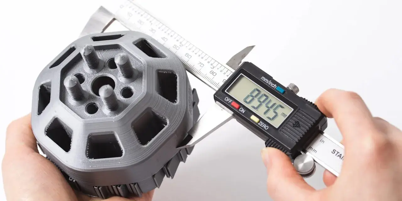
People often use precision, accuracy, resolution, and tolerance as if they were the same thing, but they solve different problems. Resolution is not the same thing as accuracy. A printer can produce fine layers and still miss critical dimensions if the material shrinks, the frame flexes, or the calibration is off. If I am judging a process for real work, I separate those terms before I look at anything else.
| Term | What it means | Why it matters |
|---|---|---|
| Accuracy | How close the printed part is to the intended size | Controls whether holes, bosses, and mating surfaces actually fit |
| Precision | How consistently the printer repeats the same result | Shows whether you can trust the machine from one run to the next |
| Tolerance | The allowed variation around the target dimension | Defines how much error the design can absorb without failing |
| Resolution | The smallest detail the process can reproduce | Limits text, edges, thin walls, and the visible stair-step pattern |
For a US shop, I still think in millimeters for design decisions, but it helps to remember that 0.1 mm is about 0.004 in. That is small enough to matter on a snap fit, a threaded insert boss, or a connector shell. Once you think in those terms, the next question becomes obvious: which process can actually hold that window?
Which printing process gives the tightest results
No single process wins every category. In my experience, desktop FDM is the most accessible place to start, but it is usually the hardest to push into truly fine tolerance territory. Resin systems, PolyJet, and industrial powder-bed processes tend to do better when the goal is crisp edges, clean features, and stable dimensions.
| Process | Typical accuracy range | Best use | Watch-outs |
|---|---|---|---|
| FDM | About ±0.5% or around ±0.5 mm in many practical jobs | Simple prototypes, brackets, enclosures, low-cost iteration | Nozzle width, shrinkage, and visible layer stepping limit fine detail |
| SLA / resin | Often around ±0.5% or roughly ±0.2 mm on small features | Detailed prototypes, masters, cosmetic parts, small assemblies | Supports, UV post-cure movement, and brittle resins can affect fit |
| SLS / MJF | Commonly around ±0.3% with roughly ±0.2 to ±0.3 mm behavior | Functional nylon parts, clips, housings, low-volume production | Powder cooling, wall thickness, and surface texture influence final size |
| PolyJet | Often near ±0.1 mm on smaller dimensions | Very fine visual prototypes and multi-material parts | Higher material cost and support cleanup can affect delicate features |
| Industrial fine-detail polymer systems | Some processes claim accuracy down to about ±40 µm | Very small holes, thin walls, and delicate, high-detail components | Usually justified only when the application needs that level of control |
That last category is where industrial systems get interesting. EOS, for example, describes a fine-detail polymer process with claimed accuracy down to about ±40 µm, which shows how far the high end can go when detail is the priority. The catch is obvious: tighter detail usually means more controlled materials, more disciplined post-processing, and a higher cost per part. That tradeoff leads directly to the real source of error, which is not just the machine, but the process around it.
What actually causes dimensional drift
Most print errors come from the interaction between heat, geometry, and handling. I see the same causes over and over again, even on good machines. If the part is only slightly off, the root cause is usually one of these:
- Material shrinkage, especially in thermoplastics and UV-cured resins, where the part moves as it cools or finishes curing.
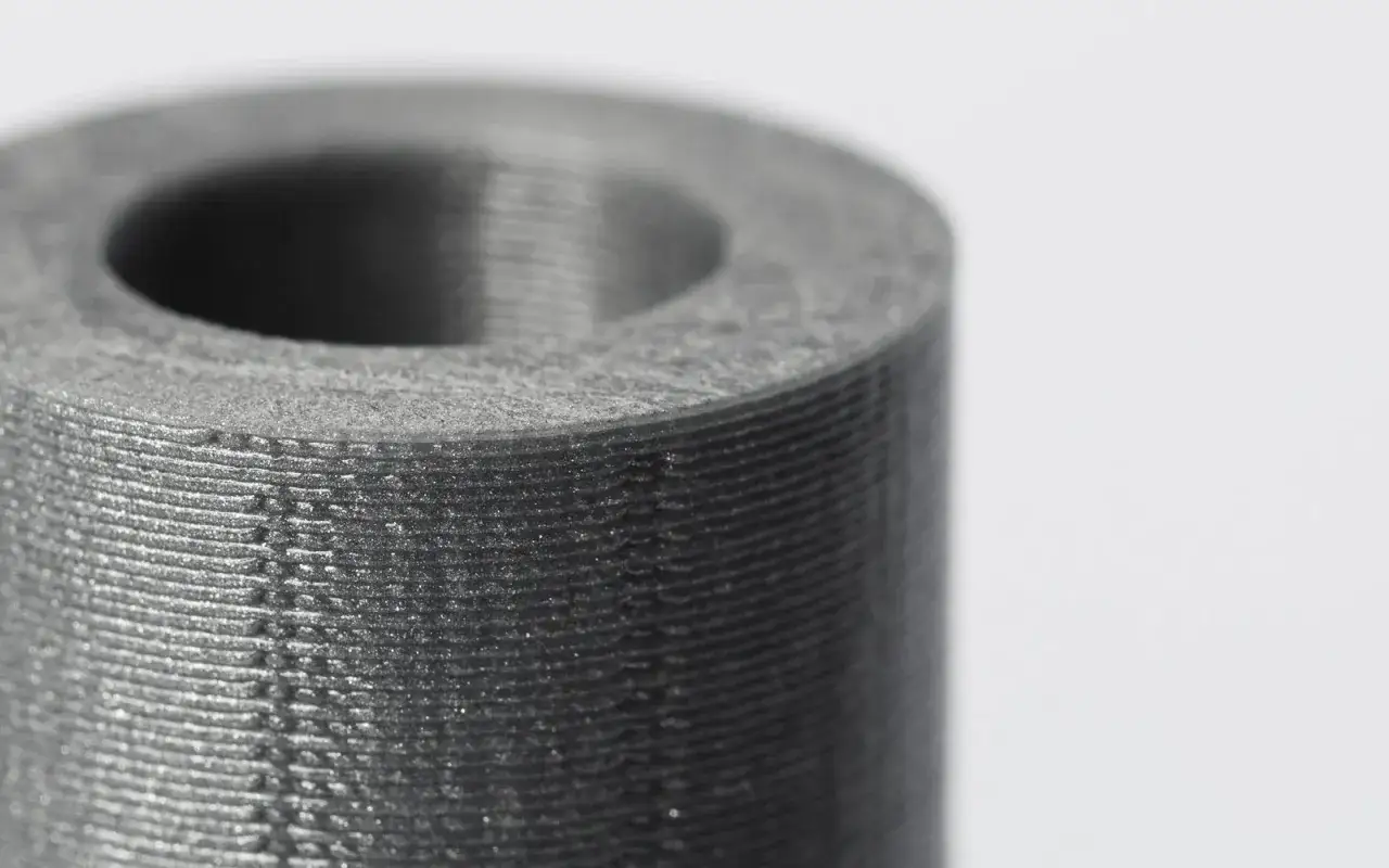
- Layer thickness, which affects stair-stepping on angled faces and how well small details survive the build.
- Support removal, which can change dimensions on the exact faces you care about most.
- Part size and geometry, because larger parts hold more heat and are more likely to warp.
- Feature size limits, since a 0.4 mm nozzle or a broad laser spot cannot reproduce every tiny groove or hole cleanly.
- Post-processing, where sanding, coating, polishing, or vapor smoothing can improve finish but also shift dimensions.
I usually pay the most attention to thermal behavior. A long, flat wall that looks harmless in CAD can pull out of square while it cools, and a supposedly simple hole can print undersized if the surrounding mass shrinks unevenly. Those are not dramatic failures, but they are enough to turn a functional fit into a rework problem. Once you understand that, the setup choices become much more deliberate.
How I set up a job for tighter tolerances
When I need a part to land accurately, I do not start with slicer speed or cosmetic settings. I start with the dimensions that actually matter, then work backward from there. The tolerance you need is the tolerance you should design for.
-
Mark the critical dimensions first. I identify the holes, bosses, snap features, and mating faces that must fit. Everything else gets less attention. That keeps the design effort focused where the failure would actually cost time or money.
-
Choose the process around the feature, not the other way around. If the part depends on tiny text, thin walls, or tight small-diameter holes, I move away from coarse FDM and toward resin or a finer industrial process. For FDM, a 0.4 mm nozzle is a sensible baseline, but truly small features often need a 0.2 mm nozzle or a different technology altogether.
-
Keep the model friendly to the material. Tall thin walls, sharp unsupported corners, and large flat spans invite warping. I try to thicken weak sections, add gentle radii where they help, and orient parts so the most important faces are not fighting gravity or support scars.
-
Calibrate with a part that reveals real fit issues. A plain cube can hide problems. I prefer a test piece that includes holes, slots, thin walls, and a few assembly features. That tells me much more about fit than a clean square ever will.
-
Measure and compensate instead of guessing. If a hole prints 0.15 mm undersize every time, I correct the CAD or slicer compensation. If a surface gains thickness after coating or polishing, I plan for that before production. Small, repeatable offsets are manageable. Random adjustments are not.
That workflow is simple, but it saves a lot of time. It also makes one thing clear: accuracy is not won by a single setting. It is built from design, calibration, and measurement working together. From there, the next step is deciding which real-world applications deserve that level of care.
Where accuracy matters most in real plastic parts
Some parts can tolerate a loose fit and still do the job. Others cannot. In plastic design work, I usually see tight tolerance requirements show up in a few predictable places:
| Application | What matters most | Why it matters |
|---|---|---|
| Snap-fit enclosures | Hole size, wall thickness, and warpage control | A tiny dimensional error can make the latch too loose or impossible to close |
| Jigs and fixtures | Flatness, repeatability, and stable reference surfaces | If the fixture is off, every part made with it is off too |
| Fluid or air guides | Sealing surfaces, thin channels, and smooth internal geometry | Leaks and pressure loss often come from minor dimensional drift |
| Visual masters and product samples | Edge sharpness and surface finish | The part has to communicate quality before it ever gets tested mechanically |
| Small connectors and inserts | Minimum feature size and hole compensation | These parts fail fast if the geometry is even slightly undercut or oversized |
For these jobs, the best material choice is often as important as the printer itself. A good resin part can outperform a mediocre FDM part for fine detail, while a nylon SLS or MJF part may be the better choice when toughness and repeatability matter more than surface polish. That balance is where practical engineering starts to beat guesswork.
The mistakes that waste accuracy fastest
I see the same errors repeated because they feel minor at the time. They are not minor once the part has to assemble, seal, or pass inspection.
- Confusing surface finish with dimensional accuracy. A smoother part is not automatically a more accurate part.
- Assuming a thinner layer solves everything. Layer height helps detail, but it will not fix bad calibration or shrinkage.
- Printing too fast for the material. Speed can amplify ringing, poor bonding, and missed dimensions.
- Ignoring support scars. If a mating face needs cleanup after support removal, the original tolerance is already gone.
- Designing nominal sizes without clearance. Real assemblies need fit allowances, especially for printed threads, holes, and sliding parts.
One practical rule I use: if the part will interact with hardware, another printed part, or an off-the-shelf component, I assume the first design is only a starting point. The fit has to be proven, not hoped for. That is why the final stage of any accurate print workflow is not the slicer, but the specification you hand off before production.
What I would specify before I send a part to print
When a client wants a tight-tolerance part, I want the request to be specific enough that no one has to guess. The more ambiguity you remove here, the less expensive the revision cycle becomes.
- List the critical dimensions and the tolerance on each one.
- State whether the fit should be loose, sliding, snug, or press fit.
- Name the process or material you prefer, if you already know the application.
- Say whether sanding, coating, polishing, or machining is allowed after printing.
- Define how the part will be inspected, especially if it must match another component.
If I had to reduce the whole topic to one sentence, it would be this: accurate parts come from controlling variation, not from hoping the printer is “precise enough.” When the design, process, and inspection method all point in the same direction, 3D printing becomes a very reliable way to make plastic parts that actually fit the job.