3D printing in aerospace has moved well past showpiece prototypes. The real value is in parts that are lighter, easier to consolidate, faster to source, or simply impossible to machine efficiently, especially when internal channels, thin walls, or complex curvature are part of the job. The catch is that flight hardware is unforgiving, so the design, material, inspection, and certification plan have to work together from the start.
What matters most before you commit to an aerospace print
- Use AM for complexity, consolidation, and lead-time reduction. If a part is simple and high-volume, conventional manufacturing still wins.
- Metal powder-bed fusion is the go-to for smaller, detailed parts; directed energy deposition and wire-fed systems make more sense when part size and deposition rate matter.
- Certification is the real bottleneck. Repeatability, feedstock control, post-processing, and inspection matter as much as the printed geometry.
- Post-processing is part of the process. Heat treatment, machining, surface finishing, and nondestructive inspection often decide whether the part is flight-ready.
- The best business case is usually a part with expensive assembly, high downtime cost, or a supply chain that is too slow or fragile.
Why aerospace keeps using additive manufacturing
I treat additive manufacturing as a design and supply-chain tool, not a universal replacement for machining or casting. It earns its place when it removes joints, cuts waste, shortens lead times, or unlocks geometry that would be awkward or impossible to make conventionally.
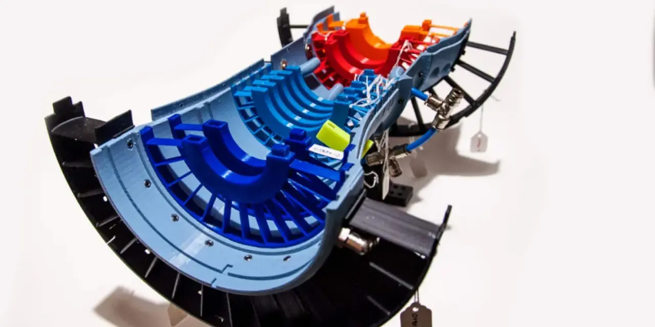
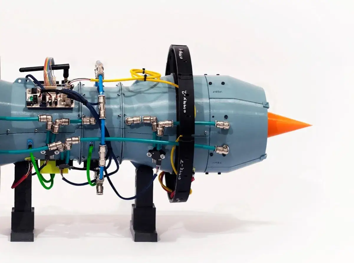
Engine hardware is the clearest proof
GE Aerospace's LEAP fuel nozzle tip is the classic example because the numbers are hard to ignore: a single printed part replaced roughly 20 welded and brazed pieces, and the nozzle tip ended up about 25 percent lighter. That kind of part consolidation is valuable not because it sounds clever, but because it removes assembly steps, interfaces, and failure points in one move.
Space systems care about the same logic, just under harsher constraints
For spacecraft and launch hardware, the payoff is often inventory reduction and mission autonomy. When a crew can print a tool, bracket, or repair part on demand, the design no longer depends entirely on what was packed before launch. That matters even more when cargo mass is tight and resupply is slow.
Tooling and factory support are where many teams start
Before flight hardware ever leaves the lab, AM often proves itself in jigs, fixtures, gauges, trim tools, and test aids. Those parts are less glamorous, but they are where teams learn the process without betting the entire program on a first article part.
Once you know why the industry uses AM, the next question is where it genuinely belongs in a product line.
Where it works best in aircraft and spacecraft
The best aerospace candidates tend to share three traits: they are hard to machine, expensive to assemble, or costly to keep in stock. That gives AM a very practical role in both aircraft and space programs.
| Application area | Why AM helps | Typical parts |
|---|---|---|
| Propulsion | Complex internal passages, heat management, part consolidation | Fuel nozzles, injectors, heat exchangers, combustion hardware |
| Airframe and cabin | Weight reduction, routing flexibility, low-volume spares | Brackets, ducts, clips, housings, cabin components |
| Tooling and factory support | Fast turnaround and lower cost for one-off equipment | Jigs, fixtures, drill templates, inspection aids |
| Space and in-space support | Cargo savings and operational autonomy | Tools, replacement pieces, experimental samples |
Not every part is a good candidate. A simple bracket in a high-volume platform may be cheaper and easier to stamp, machine, or forge. AM starts to win when the geometry is difficult, the production volume is modest, or the cost of a missing spare is much higher than the cost of making one.
That application map narrows the process choices, because not every printer solves the same problem.
Which processes and materials are actually worth considering
Process choice decides most of the economics. In aerospace work, I usually start with powder-bed fusion, directed energy deposition, and a smaller set of polymer processes for tooling and non-structural use.
| Process | Best fit | Strengths | Tradeoffs |
|---|---|---|---|
| Laser powder bed fusion | Small to medium metal parts with fine detail | High resolution, complex geometry, strong fit for internal channels | Slower builds, powder handling, support removal, size limits |
| Electron beam powder bed fusion | High-performance metal parts where vacuum processing is acceptable | Good for certain alloys, useful thermal control, robust fusion | Surface finish and equipment complexity can be challenging |
| Directed energy deposition | Large near-net-shape parts and repairs | Higher deposition rates, larger build envelope, material efficiency | Lower detail resolution, machining usually needed afterward |
| Wire-fed directed energy deposition | Large titanium or structural parts | Good material utilization, strong fit for near-net shapes | Requires careful finishing and process control |
| Material extrusion and reinforced polymers | Tooling, fixtures, ducts, and non-flight parts | Low entry cost, quick iteration | Limited temperature and structural capability |
The material matters just as much as the process. Titanium alloys are favored where strength-to-weight and corrosion resistance matter. Nickel alloys belong near high-temperature propulsion hardware. Aluminum still has a place in lighter structures and housings, but it is more sensitive to process control. Polymers and fiber-reinforced thermoplastics are often the smartest route for tooling, ducting, and test hardware rather than primary structure.
FAA guidance for powder-bed-fusion engine parts makes the point clearly: the compliance path is built around material control, process control, and post-process control, not just a successful print. That is why feedstock spec, thermal treatment, metallography, and mechanical properties have to be managed as a chain, not as separate paperwork tasks.
Once the process is chosen, the certification and quality story becomes the real gate.
Certification and quality control are the real gatekeepers
In U.S. aerospace, a part is not ready because it printed cleanly. It is ready when the company can prove repeatability across machines, builds, and lots, and when the inspection plan can show that the part consistently meets the design intent.
NASA-STD-6030 is a good example of how serious this gets. It sets minimum requirements for spaceflight hardware produced by additive manufacturing, covers crewed and uncrewed systems, and even addresses in-space AM operations. The message is simple: if the part is critical, the controls around it have to be just as mature as the printer itself.
- Feedstock control means powder or wire chemistry, storage, reuse, and contamination limits are defined.
- Machine qualification means the hardware, software, calibration, and maintenance state are stable enough to trust.
- Part production plans define build orientation, support strategy, scan strategy, and inspection points.
- Post-process plans cover stress relief, hot isostatic pressing, machining, surface finishing, and final inspection.
- Evidence of capability matters more than one good coupon; repeatability is what gets programs over the line.
I would be wary of any proposal that talks mostly about the printer and barely about inspection, traceability, or post-processing. In aerospace, that is usually where the schedule and cost surprises hide.
That is why design discipline matters just as much as machine capability.
Design rules that separate useful parts from expensive demos
AM rewards parts that are designed for the process. It punishes teams that try to print an old machined design unchanged and hope the layer-by-layer method will forgive the mismatch.
Consolidate assemblies only when the joints are the problem
Part consolidation is powerful when it removes fasteners, seals, welds, or brazed interfaces that create inspection burden or failure risk. It is less useful when the assembly already works well and the consolidation would simply move complexity into qualification.
Design for supports, escape paths, and inspection
Internal channels need powder-removal paths. Overhangs need support strategy. Critical surfaces need a finishing plan. If a part cannot be inspected or cleaned properly after printing, the geometry may be elegant but the program is still stuck.
Read Also: SLS TPU - Design Flexible Parts That Actually Work
Expect post-processing to shape the final cost
For flight hardware, the printer is only one station in the route. Heat treatment stabilizes properties, machining hits tolerances, and nondestructive inspection looks for hidden flaws. If a part depends on several expensive secondary steps, the business case needs to survive those additions, not just the raw print time.
- Avoid ultra-thin walls unless the alloy, process, and build orientation have been proven.
- Do not assume the printed part will match final tolerance without machining.
- Do not create internal features that trap powder or make inspection impossible.
- Do not qualify one machine and assume every machine behaves the same.
- Do not build the ROI case on material savings alone.
When teams design around these rules, additive manufacturing becomes a production tool instead of a science project. From there, the adoption plan is mostly about sequencing, evidence, and cost control.
A realistic adoption path for U.S. aerospace teams
If I were guiding a program, I would not start with a primary flight-critical structure. I would start where the risk is lower and the learning curve is still valuable.
- Begin with tooling, fixtures, or non-flight parts. That gives the team a way to learn machine behavior, finishing, and inspection without tying the whole program to the first build.
- Pick one part with a clear pain point. The best candidate usually has complex geometry, supply-chain friction, or an assembly that is too expensive to maintain conventionally.
- Lock the acceptance criteria before redesigning the part. Strength, surface finish, dimensional tolerance, and inspection method should be agreed up front.
- Qualify the chain, not just the machine. Feedstock, software, machine state, heat treatment, machining, and NDT all need to be controlled together.
- Scale only after the data is boring. Repeated, boring results are what aerospace programs want. Exciting results usually belong in the lab, not the fleet.
There is also a simple financial filter I use: if the part only becomes attractive when you ignore post-processing, inspection, or qualification labor, the case is too weak. If the part saves assembly time, reduces inventory, or removes a known reliability problem, the case is much stronger.
The next gains will come from tighter process control, better inspection, and hybrid workflows, not from hype.What I would watch next as aerospace printing matures
The most interesting progress is happening in three places. First, larger near-net-shape metal parts are making DED and wire-fed systems more practical for structural applications. Second, in-space manufacturing is shifting from demonstration toward operational usefulness, which matters for long-duration missions and on-orbit repair. Third, hybrid manufacturing is closing the loop by combining printed geometry with conventional machining, so engineers can get both shape freedom and tight tolerances.
That is the direction I would trust in 2026: fewer headline-grabbing demos, more repeatable hardware with a clear qualification path. If a part can be printed, inspected, finished, and traced as a controlled process chain, it has a real aerospace future. If it cannot, it is still probably a prototype.