The decisions that matter before the first tool is cut
- Thermoforming starts with a flat sheet, so draw ratio and thickness variation shape almost every decision.
- Injection molding gives tighter dimensional control, but it punishes poor wall transitions, weak draft, and bad ejection strategy.
- Draft is not optional: a practical starting point is about 2° on female thermoform tools, 4° on male tools, and roughly 1° to 2° on many injection-molded faces.
- Radii, texture, and cooling often matter as much as nominal dimensions.
- The cheapest fixes usually come from simplifying geometry early, not from forcing the tool to rescue a bad part.
What good tooling has to solve in thermoforming and injection molding
I start every project by asking a simple question: what problem is the tool actually solving? In thermoforming, the answer is usually how to stretch a heated sheet without thinning it too much, how to release it cleanly, and how to keep the part stable after trimming. In injection molding, the tool has to fill evenly, vent air, cool in a controlled way, and eject the part without leaving drag marks, warpage, or sink.That sounds obvious, but it changes the entire way I read a drawing. A thermoformed part is not controlled the same way as an injection-molded one. In thermoforming, only the mold side is truly governed by the tool, so I treat the opposite side as a variable rather than a promise. In injection molding, the mold can define both sides, but it also introduces more complexity around gating, cooling balance, and ejection.
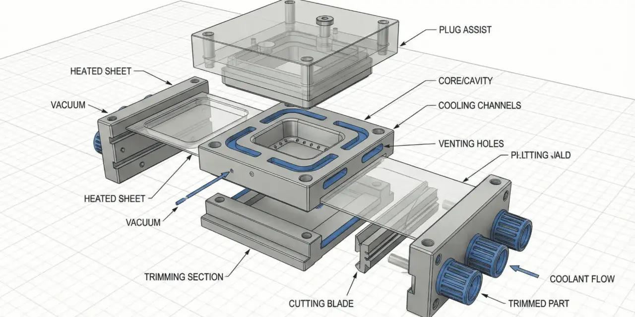
Thermoforming starts with a sheet, not a cavity
Thermoforming begins when a plastic sheet is heated, draped over a male or female tool, and pulled into shape with vacuum or pressure. Because the material is stretched from a flat plane into a three-dimensional form, the wall thickness will never stay perfectly uniform. The deeper the draw, the more the sheet thins, especially around sharp corners and tight details. In many design guides, a stretch ratio around 3:1 is treated as a practical upper boundary for ordinary forming conditions, and plug assist is often used when the draw gets aggressive or multiple features sit close together.
That is why I do not treat thermoforming like a cosmetic version of injection molding. It is a different physics problem. The tool has to help material distribution, not just shape the outer surface. That difference is where the rest of the design rules come from.
Injection molding starts with flow and ends with ejection
Injection molding behaves differently because molten resin is forced into a matched core-and-cavity tool. The part can be highly detailed, but the design has to support the whole cycle: fill, pack, cool, and eject. If one wall is too thick, it cools slower and can create sink or warp. If draft is weak, the part drags on the tool surface during ejection. If the part has deep internal features, you may need side actions, slides, or a different geometry altogether.
That is why I usually think of injection molding as a system problem. The part, the tool, the resin, and the cycle all have to agree. Once they do, production becomes predictable. When they do not, the mold tells you quickly. The next step is comparing the two processes directly, because the tradeoffs are easier to see that way.
Thermoforming and injection molding are solved differently
| Criterion | Thermoforming | Injection molding | Why it matters |
|---|---|---|---|
| Tool structure | Usually a single-sided male or female form tool | Matched core and cavity with a closed fill system | Single-sided tools are simpler, but they control less of the final geometry. |
| Detail level | Good for enclosures, panels, trays, and large shapes; pressure forming improves detail | Best for tight detail, undercuts, snaps, and functional micro-features | If the part needs crisp internal geometry, molding often wins. |
| Draft | A common starting point is about 2° on female tools and 4° on male tools | Many parts work well around 1° to 2°; textured surfaces need more | Release behavior is one of the fastest ways to make or break the tool. |
| Wall behavior | Thickness changes with draw depth and material stretch | Wall thickness should stay as uniform as possible | Thermoformed parts are limited by thinning; molded parts are limited by cooling balance. |
| Tooling cost and lead time | Usually lower upfront cost and shorter lead time | Usually higher upfront cost and more tool complexity | This often decides whether a project starts with a formed part or a molded one. |
| Typical fit | Large, moderately detailed parts where cost and speed matter | High-volume parts with tighter dimensional and functional demands | The right process is usually the one that supports the part instead of fighting it. |
Pressure forming sits in the middle when a project needs more detail than vacuum forming can comfortably deliver. In practice, compressed air can run roughly from 10 to 120 PSI during pressure forming, which is why the process can reproduce sharper surface detail than basic vacuum forming. When I see a part with a logo recess, fine ribs, or a more cosmetic exterior, I immediately ask whether pressure forming is enough or whether injection molding is the better long-term fit. That question is usually cheaper to answer early than after the first failed tool.
How I build the design workflow before cutting a tool
I rarely start with dimensions alone. I start with function, release direction, and which surface has to look or perform the best. That order matters because the first sketch often decides the parting line, the draw direction, and whether a feature is realistic in the chosen process. If those choices are wrong, every later revision becomes a compromise instead of an improvement.
- Define the part’s job and identify cosmetic surfaces, mating surfaces, and load-bearing areas.
- Choose the process before finalizing geometry. A good thermoformed enclosure and a good injection-molded enclosure will not follow the same rules.
- Lock the pull direction and parting line early so draft and undercuts can be evaluated honestly.
- Set wall targets, radii, and transitions before adding detail features like bosses, ribs, logos, or vents.
- Plan cooling, venting, trimming, and ejection together instead of treating them as separate afterthoughts.
- Review the model with the molder or toolmaker while changes are still cheap.
For thermoforming, I pay close attention to how the sheet will distribute across the mold face. A deep pocket, a tight corner, or two features too close together can distort the whole part. For larger parts, I also want the drawing to specify the temperature at which dimensions will be checked, because thermal expansion can move a large part enough to matter. For injection molding, I want the gate, venting, and ejection strategy sketched as clearly as the cosmetic surfaces. If those are invisible in the CAD review, they will show up later as defects.
Once the workflow is clear, the real work becomes geometry control: draft, wall thickness, corners, and undercuts. That is where most costly revisions begin.
Geometry rules that prevent thinning, drag, and warp
Keep walls honest
In injection molding, I aim for uniform wall thickness whenever possible. A useful rule of thumb is that ribs, gussets, or boss walls should be about 40% to 60% of the adjacent wall thickness. Thicker sections cool slower, which creates sink, stress, and dimensional drift. In thermoforming, the issue is different but related: the material is pulled from a flat sheet, so any deep draw creates thinner areas by default. A geometry that looks harmless in CAD can become weak at the corners once it is formed.
My rule is simple: if a feature gets thicker for no functional reason, I challenge it. If a feature gets thinner because the sheet has to stretch too far, I challenge that too. The cleanest parts usually come from the most disciplined thickness strategy.
Use draft as a release strategy
Draft is not decoration. It is the angle that lets the part leave the tool without scraping, sticking, or hanging up. In thermoforming, a practical starting point is about 4° on male tools and 2° on female tools, with more draft required for deeper parts or nested parts. In injection molding, 1° to 2° works well in many situations, while textured surfaces and shutoffs need more. If the mold surface is textured, I assume the required draft will increase because texture behaves like a series of micro-undercuts.
When draft is missing, the failure mode is rarely elegant. You get scuffing, stuck parts, stress at ejection, or damage to the polished surface. I would rather redesign a wall by a degree than rescue a scratched finish after tool steel has already been cut.
Read Also: Overmolding Explained - The Ultimate Guide to Multi-Material Parts
Radii and undercuts need a realistic plan
Sharp three-sided corners are one of the easiest ways to thin a thermoformed part too far. The deeper the draw, the larger the radius or chamfer should be. A small cosmetic corner may survive in CAD, but in the mold it can force the material over too much surface at once and pull the gauge down to an unacceptable level. In injection molding, sharp internal corners are also a problem because they concentrate stress and encourage warp.
Undercuts deserve the same honesty. If the undercut is shallow, flexible, or easy to release, fine. If it is not, I want a moveable section, a designed witness line, or a different geometry. That is especially important in thermoforming, where one-sided release is already doing most of the work. The more a design relies on hope, the more likely it is to require a revision.
Materials, cooling, and surface finish decide how the tool behaves
Tool material is not just a procurement choice. In thermoforming, aluminum is widely favored because it conducts heat well and supports more consistent cooling cycle times. That is why controlled cooling and stable mold temperature matter so much. If the tool cannot manage heat predictably, the part will not hold dimensions consistently from cycle to cycle. Wood, epoxy, and plaster may work for niche prototypes, but they are not the answer when temperature control and repeatability matter.
The resin choice matters just as much. Amorphous materials usually give a wider forming window, which makes them easier to work with. Semi-crystalline materials tend to have a narrower window and demand tighter control over temperature and cycle timing. I also pay attention to the stability of the sheet itself, because extrusion variation, stored stress, and seasonal temperature swings can all shift final dimensions. On large thermoformed parts, I want the drawing to state how and at what temperature measurements will be taken.Surface finish is another place where teams underestimate the tool. A polished surface releases differently from a textured one. Texture can improve appearance and grip, but it also increases release friction and usually demands more draft. In thermoforming, texture can effectively behave like a chain of tiny undercuts. In injection molding, the same idea applies: a textured wall needs a more generous release strategy than a smooth one.
I think of cooling, finish, and material as a three-part agreement. If one of them is ignored, the tool may still run, but the part will usually tell you something is off. The last section is about those warning signs and how to avoid them before they become expensive.
The mistakes that force a redesign
| Mistake | What it usually causes | Better move |
|---|---|---|
| Choosing geometry before choosing the process | Parts that are technically possible but expensive to tool | Set the process first, then design around its limits. |
| Ignoring draft on prototype CAD | Sticking, scuffing, and painful redesigns later | Build draft into the first model, even if the prototype is not molded yet. |
| Making ribs, bosses, or thick islands too large | Sink, warp, and uneven cooling | Keep support features in the 40% to 60% wall range. |
| Using sharp corners in a deep thermoform draw | Thinning, tearing, and weak corners | Use larger radii or chamfers where the draw is deepest. |
| Building undercuts without a release plan | Slides, witness lines, or a part that will not release cleanly | Minimize the undercut or design a controlled moving section. |
| Forgetting that finish changes draft needs | Scratch marks and texture lock | Increase draft when texture or cosmetic finish is part of the spec. |
The common thread is simple: bad tooling decisions almost always start as design decisions. That is why I push for early DFM review instead of waiting for a finished CAD model to be judged at the last minute. A ten-minute design conversation can save a week of tool rework. More importantly, it can keep the part aligned with the process instead of forcing the process to absorb a bad choice.
What to confirm before you release the tool for production
Before I green-light a tool, I want six things confirmed: the pull direction is locked, the parting line is defensible, draft matches the finish, wall transitions are controlled, cooling or heat management is realistic, and the tolerance scheme matches how the part will actually be measured. If any of those are vague, I assume the risk will come back later as scrap or rework.
- The part can release without relying on force or operator luck.
- Texture, polish, and draft are coordinated instead of treated separately.
- Deep draws have enough radius, or the part has been simplified.
- Wall thickness changes are intentional, not accidental.
- Trimming and inspection conditions are part of the drawing, not informal shop knowledge.
- The molder has signed off on the manufacturability details before steel or aluminum is cut.
If I had to reduce the whole topic to one sentence, it would be this: the best tool is the one that anticipates release, heat, and material flow instead of merely matching the CAD file. That mindset is what keeps thermoforming efficient and injection molding repeatable. When the part, the process, and the tool all agree, production feels calm for a reason.