Selective laser sintering sits in a useful middle ground: it gives you nylon-based components that are tough enough for real use, complex enough to replace assemblies, and practical enough for small batches. In this article I focus on what the process actually produces, where it works best, how to design around its limits, and what to expect from finishing, cost, and turnaround. For many SLS parts, the surface is secondary to fit, strength, and repeatability.
I keep the emphasis on decisions that matter on the shop floor, not just in a CAD screenshot. If you are weighing housings, clips, fixtures, or low-volume production runs, the details below will help you decide whether this process fits the job.
The essentials at a glance for powder-bed nylon parts
- The process builds parts layer by layer from powder, so it does not need separate support structures.
- It is strongest when used for functional prototypes, jigs, fixtures, snap fits, housings, and small production runs.
- A safe design starting point is around 0.8 to 1.0 mm wall thickness, with 0.5 to 0.6 mm clearances for moving features.
- Drain holes matter: enclosed cavities should have at least two exit points, and 3.5 mm is a practical minimum diameter.
- PA12 is the workhorse material, PA11 is better when impact and flexibility matter, and TPU adds elastic behavior.
- Surface finishing can improve appearance and sealing, but it also adds time and can affect tight fits.
What makes these nylon parts different from other 3D prints
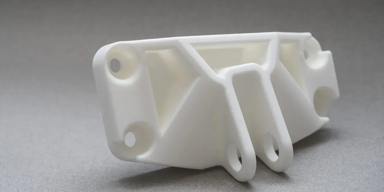
Selective laser sintering is a powder-bed fusion process. A laser selectively fuses polymer powder, the bed drops, a fresh layer is spread, and the cycle repeats until the part is complete. The important detail is that unfused powder supports the geometry during the build, which is why the process can handle internal channels, undercuts, and nested assemblies without the support scars you get from many other 3D-printing methods.
That support-free behavior changes the way I think about the part. Instead of designing for support removal, I design for powder removal, heat control, and consistent wall behavior. The parts usually come out in nylon or nylon-like powders, so they tend to be tough, lightweight, and functional rather than glossy or jewelry-smooth. They are not fully injection-molded plastic, but for many engineering uses they get close enough in strength and practicality to replace a machined or molded part early in the development cycle.
Layer thickness is typically around 100 to 110 microns on modern systems, which is fine enough for details but still visible on smooth faces. That is why the process rewards honest geometry more than cosmetic geometry. Once you understand that difference, the next question becomes where it actually pays off in a project.
Where the process earns its keep
I reach for this process when the part has to do real work, not just look correct. It is especially useful when geometry, batching, and functional performance matter more than a polished surface.
- Enclosures and housings. Electronics covers, sensor shells, and equipment housings benefit from the ability to add internal ribs, clips, and cable routes without support cleanup.
- Jigs and fixtures. Custom workholding and assembly aids are a good fit because they often need to be light, durable, and easy to revise between production jobs.
- Snap-fit assemblies. The process works well for clips, latches, and simple compliance features when the material choice matches the amount of flex you need.
- Ducting and fluid-path components. Complex channels and airflow paths are easier to make because the powder itself supports the build during printing.
- Low-volume end-use parts. If you need tens or hundreds of units before tooling makes sense, batching parts in one build can be more economical than forcing the geometry into an early mold.
The weak spot is also clear: if the part must look perfectly smooth straight out of the printer, this is usually not my first choice. I would rather use it for a part that needs to survive handling, load, vibration, or repeated assembly, then finish it only as much as the application justifies. That leads directly to the design rules that keep the process predictable.
Design rules that prevent expensive reprints
The biggest mistakes are usually not dramatic. They are small geometry decisions that look harmless in CAD and become expensive once powder is trapped, a wall is too thin, or a fit is too tight. Here is the baseline I use when I want a build to come out clean the first time.
| Feature | Practical starting point | Why it matters |
|---|---|---|
| Wall thickness | 0.8 to 1.0 mm for production-minded parts | Thinner walls can warp, feel fragile, or lose detail during cooling. |
| Minimum printable wall | About 0.6 mm on some systems | Possible in controlled cases, but I would not rely on it for high-stress geometry. |
| Moving clearance | 0.5 to 0.6 mm | Leaves room for movement and for powder to escape from nested features. |
| Drain holes | At least 2 holes, 3.5 mm or larger | Prevents trapped powder in hollow parts and makes depowdering far easier. |
| Layer thickness | 100 to 110 microns | Fine enough for usable detail, but not a substitute for finishing on cosmetic faces. |
| General tolerance on well-designed parts | About ±0.25 mm plus 0.0015 mm/mm | Useful for planning fits, but the exact machine and material still matter. |
Three habits save the most time in practice. First, I keep wall thicknesses as uniform as possible, because random thick-to-thin transitions invite distortion. Second, I add generous fillets at interior corners instead of leaving sharp stress points. Third, I make sure every cavity has a realistic path for powder to leave, because trapped powder causes more failures than most people expect.
Once those basics are in place, you can start thinking about materials and finishing choices, which often decide whether the part feels merely printable or genuinely production-ready.
Materials and finishes that change the result
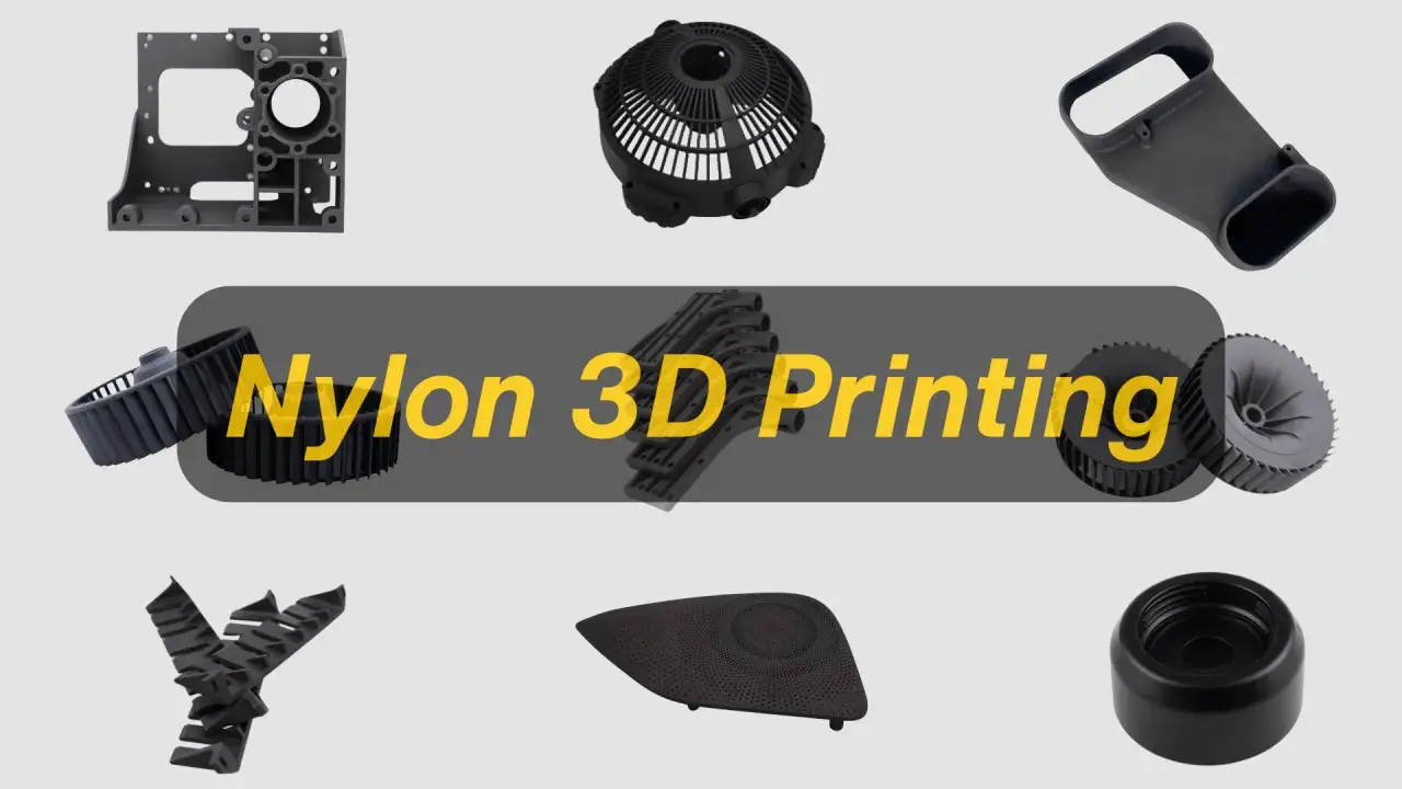
Most selective laser sintering work starts with nylon, but not all nylon powders behave the same way. The material choice affects stiffness, impact resistance, flexibility, heat behavior, and how the surface feels in the hand.
| Material family | What it does well | Tradeoff | Good uses |
|---|---|---|---|
| PA12 | Balanced strength, stiffness, chemical resistance, and dimensional stability | Rougher cosmetic finish than SLA and only moderate flexibility | General-purpose housings, brackets, functional prototypes |
| PA11 | Better ductility and impact resistance, with more forgiving flex | Usually less stiff than PA12 | Clips, hinges, snap-fits, wearable or impact-prone parts |
| TPU | Elastic behavior and vibration damping | Not a substitute for rigid load-bearing plastic | Seals, gaskets, cushioning features, flexible covers |
| Glass- or carbon-reinforced nylon | Higher stiffness and better structural response | Can become more brittle, especially in thin or highly stressed sections | Fixtures, structural brackets, parts that need extra rigidity |
Finishing changes the story almost as much as the powder does. Bead blasting removes loose powder and evens out the grain. Dyeing is common when the part needs color consistency without painting. Vapor smoothing can improve surface quality and porosity, but it also rounds edges and can alter tight fits, so I treat it as a design decision rather than a cosmetic afterthought. Coatings can add wear or chemical resistance, yet they are only worth paying for when the end use justifies the extra step.
My rule is simple: choose the material for function, then choose the finish for the job the part has to perform in the hand, in the machine, or in the market. If you are trying to force one powder and one finish to do everything, the compromise usually shows up somewhere else.
What drives cost and lead time
The real cost of a build is not just the print itself. It is the volume of the part, how well it nests with other parts, how much powder has to be removed, and how much finishing or inspection you want before shipment. Because the process does not need dedicated supports, it can pack many parts into a single build, and that is where SLS becomes especially economical for small batches.
Lead time is often shorter than people expect. Straightforward jobs can be turned around in as fast as one day, but that is only part of the picture. Depowdering, bead blasting, dyeing, vapor smoothing, and dimensional inspection can easily add more calendar time than the print itself. In practice, I expect the raw build to be quick and the finish package to be the real schedule lever.
When I look at a quote, I pay attention to four things first: the part volume, the number of parts that can share one build, the selected material, and whether the part needs cosmetic finishing. Those four variables explain most of the price difference I see between a simple functional bracket and a polished, customer-facing enclosure. That also makes it easier to compare SLS with the other mainstream 3D-printing options.
How it compares with MJF, FDM, and SLA
People often compare powder-bed nylon against every other 3D-printing process, but each one solves a different problem. I would not choose them interchangeably.
| Process | Best when you need | Main tradeoff |
|---|---|---|
| Selective laser sintering | Tough nylon parts, complex geometry, nested builds, and functional prototypes or production runs | Rougher surface finish than some alternatives |
| Multi jet fusion | Similar nylon functionality with a slightly finer surface and crisp detail in many cases | Process and material ecosystem can be narrower depending on supplier |
| FDM | Low-cost iteration, simple geometry, and quick proof-of-concept parts | Visible layer lines, support marks, and weaker consistency across axes |
| SLA | Sharp visual detail, smooth surfaces, and presentation models | Less forgiving for load-bearing functional parts and support cleanup is unavoidable |
If I need a part to look clean and carry a light load, SLA might win. If I need the cheapest possible proof of shape, FDM usually wins. But when the part has to be tough, complex, and practical without support scars, powder-bed nylon is still the option I reach for most often. The choice becomes even clearer once you run the final checklist before release.
The checklist I use before approving a build
Before I send a model into production, I run through the same short list every time. It is not complicated, but it catches the failures that are most expensive to fix after the fact.
- Confirm the exact powder and machine, not just the process family.
- Check every wall, rib, and boss against a realistic thickness target.
- Give every enclosed cavity a powder exit strategy.
- Set clearances for moving or nested features before you commit to production.
- Decide whether the part will stay as-printed or receive blasting, dyeing, smoothing, or coating.
- Validate one critical fit with a test build if the assembly has tight tolerances.
For most SLS parts, the biggest gains come from design discipline rather than exotic settings. If you keep the geometry powder-friendly, choose the right nylon, and plan finishing early, the process is one of the most reliable ways to move from prototype to production without redesigning the part twice.