
Rounded corners look simple until you have to match one across a prototype, a mold, and a drawing. In product design, a radius affects fit, strength, tool access, and how a part behaves in plastic, so the measurement needs to be more than a visual guess. This article focuses on how to measure rounded corners on plastic parts, molded enclosures, and machined features without guessing.
The fastest path to an accurate corner measurement
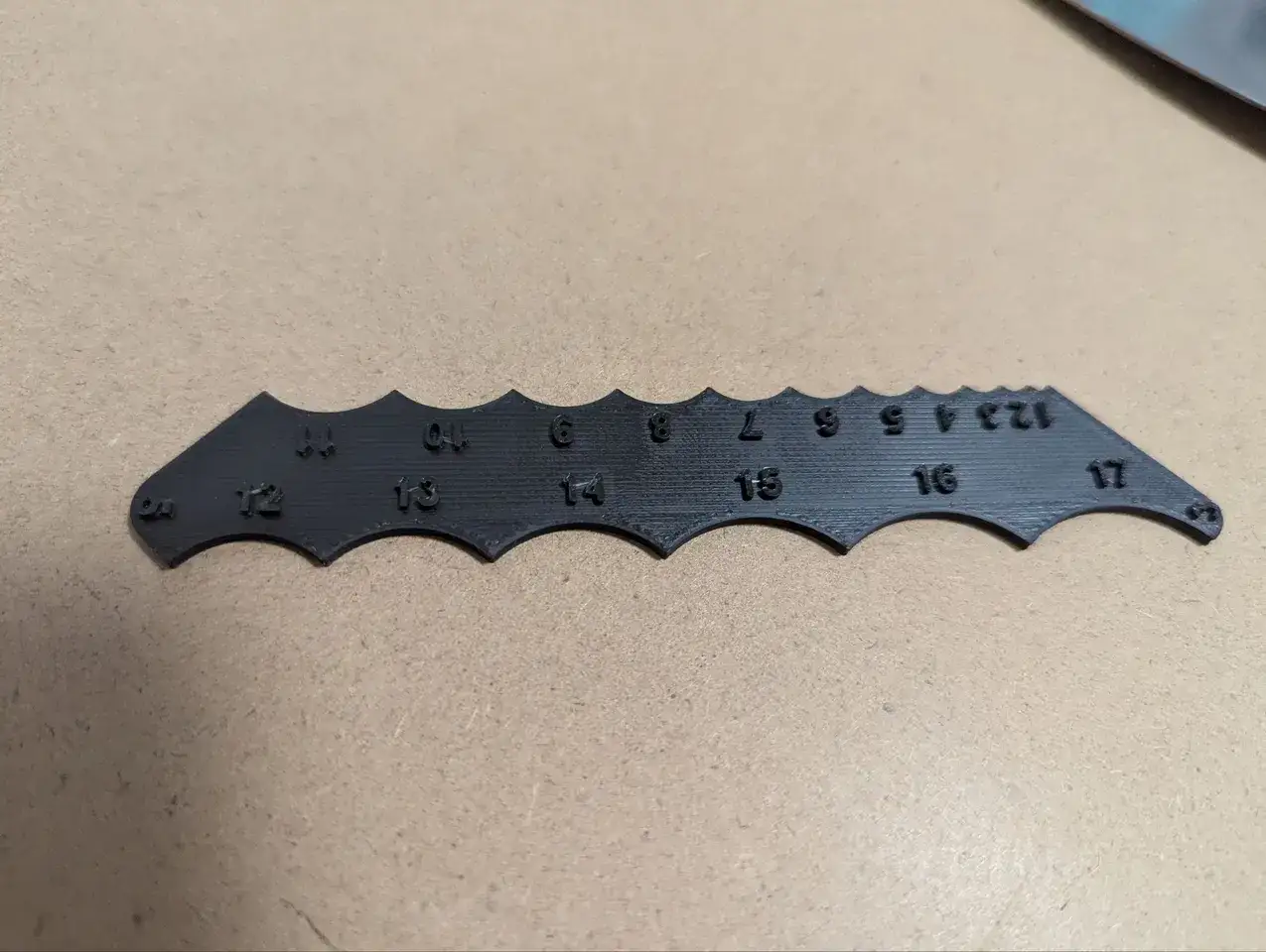
- Radius gauges are the quickest shop-floor check when you need a pass/fail answer.
- Chord and sagitta give you a real number when the drawing or inspection report needs a dimension.
- Internal and external corners are not measured the same way, and a visual match can still be wrong.
- In plastic product design, larger radii often reduce stress and improve flow, but the right value still depends on wall thickness and geometry.
- If the corner is critical, confirm it with metrology equipment instead of relying on touch or eye alone.
What you are actually measuring
I start every corner check with one question: is this a true circular radius, or just a blended edge that looks rounded? That distinction matters because a true radius can be measured cleanly, while a blend may only give you an approximate fit.
On a drawing, the number usually refers to the radius, not the diameter. The radius is the distance from the center of the arc to the curve itself. In practice, that means you are measuring the shape that connects two straight faces, not just the soft-looking transition at the outside of the part.
For plastic parts, I also separate internal fillets from external radii. An internal fillet sits where two faces meet inside a corner. An external radius softens the outside edge. They may appear related, but they do not always share the same tooling limits or design intent. Once that distinction is clear, the choice of tool becomes much less subjective.
The fastest way to check a radius on the shop floor
For a fast inspection, I usually reach for a radius gauge set first. These gauges let you compare the part directly against known radii, which is ideal when you want a quick yes or no without doing any math. Common sets cover a useful spread of sizes, often from about 0.5 to 15 mm or from 1/64 to 1/2 inch depending on the set.
| Method | Best use | Strength | Limitation |
|---|---|---|---|
| Radius gauge | Quick shop-floor checks | Fast, simple, inexpensive | Only works well when the corner matches a true radius |
| Calipers plus formula | Documenting a numeric radius | Produces a defensible value | Needs access to the chord and depth |
| Template or printed profile | Prototype screening | Cheap and flexible | Less precise than metal gauges |
| CMM or vision system | Tight tolerances and production release | Best for complex geometry | Slower and more expensive |
The practical trick is not to force a leaf into place. The correct gauge should sit naturally against the arc with no obvious rocking and no daylight gap that keeps changing as you move it. If the part is tiny or the corner is buried in a pocket, I use a smaller gauge, a profile template, or optical inspection rather than pretending a bad fit is good enough. When the fit is uncertain, that is usually your cue to move from matching the shape to measuring the geometry.
The chord-and-sagitta method when you need a number
When the part has to be documented, I stop eyeballing and measure the arc as geometry. The cleanest manual method is to record the chord and the sagitta. The chord is the straight-line distance across the opening, and the sagitta is the depth from the midpoint of that chord to the arc.
Use this formula for a true circular arc:
R = (c2 / (8h)) + h/2
where R is the radius, c is the chord length, and h is the sagitta. Keep the units consistent, and the result will come out in the same unit system.
A simple example: if the chord is 20 mm and the sagitta is 1 mm, the radius is 50.5 mm. That is the kind of answer a caliper-based inspection can support when you need something more precise than a gauge match.
This method is strongest when the corner is a true arc. If the edge is a compound blend, a worn toolpath, or a molded transition that changes curvature, the result becomes an effective radius rather than a perfect design radius. That is still useful, but it should not be confused with a strict geometry callout. That limitation leads directly to the mistakes I see most often on real parts.
Where most radius measurements go wrong
The biggest mistake is measuring from the wrong place. People often place the chord too far into the straight section, or they start the measurement before the corner has truly left the tangent. The result is a number that looks reasonable but does not represent the actual arc.
- Mixing radius and diameter is still common, especially when teams switch between inch and metric references.
- Measuring a blend as if it were a circle can give a misleading radius, even when the gauge seems to fit.
- Ignoring surface finish can distort the apparent edge on textured, painted, plated, or printed parts.
- Checking only one side of the feature is risky when the inside and outside corners were machined or molded differently.
- Forgetting the tolerance makes a measured radius meaningless if the acceptable band was never defined on the drawing.
I also watch for manufacturing artifacts. On molded parts, parting lines, draft, and polish can make a corner look sharper or softer than it really is. In machined tooling, the internal corner may be limited by the cutter used to form the mold cavity, so the measured part reflects both the CAD intent and the tooling reality. Once you know those limits, you can read the part without fooling yourself.
Why radii matter in plastic product design
Rounded corners are not just an inspection problem. In plastic design, they directly affect stress, fill behavior, and part durability. Sharp internal corners concentrate stress and can encourage warp or cracking, especially in thin walls or glass-filled materials. A thoughtful radius gives the material a smoother path and usually makes the part more forgiving in production.
| Corner type | Common starting point | Why it helps |
|---|---|---|
| Internal fillet | About 0.5 x adjacent wall thickness | Reduces stress and helps molten plastic flow into the corner |
| External radius | About 1.5 x nearby wall thickness | Softens the edge and lowers residual stress |
I treat those numbers as starting points, not laws. Material choice, wall thickness, draft, and part geometry can push the ideal radius up or down. A glass-filled nylon housing, for example, usually needs more respect than an unfilled cosmetic cover. The important part is that the radius should support the function of the part, not just make the model look polished in CAD.
That is why I never separate measurement from design intent. If the corner is meant to improve fit, reduce stress, or control the toolpath, the inspection method has to confirm that behavior, not just the shape on screen. With that in mind, the last step is deciding how I would verify the part before I release it.
What I would verify before releasing the drawing
When I am responsible for a part, I use a short sequence that keeps the inspection honest and repeatable.
- Confirm whether the feature is an internal fillet, an external radius, or a blended transition.
- Check the drawing for the stated radius and tolerance before touching the part.
- Use a radius gauge for a fast match if the feature is accessible and clearly circular.
- Measure chord and sagitta when I need a recorded value that can stand up in review.
- Escalate to a CMM, vision system, or contour measurement tool when the part is critical or the shape is complex.
- Record the result in the same unit system the team uses on the drawing, and avoid vague notes like "rounded edge."
If I could give one practical rule, it would be match the method to the decision. A gauge is enough for a quick pass/fail check, but a production release, a mold correction, or a customer dispute deserves a number you can defend. That is the difference between a part that merely looks right and one that is actually controlled.