Machined prototypes are still one of the fastest ways to turn a CAD model into something you can hold, test, and modify with confidence. The real value is not just speed; it is the combination of dimensional accuracy, material realism, and a surface finish that tells you how the part will behave in use. This article looks at subtractive manufacturing for prototyping and production, where it fits best, where it wastes time, and how to design plastic parts so the first cut is close to right.
What matters most before you order a machined prototype
- Start with the part’s job, not the machine. Fit, load, finish, and volume decide the best process.
- Machined prototypes are strongest when you need real material behavior, tight geometry, and quick design changes.
- Plastic parts need extra attention on wall thickness, corner radii, clamping, and moisture-sensitive grades.
- Setup count and fixturing often influence cost more than spindle time.
- Printing is better for complex internal shapes; molding wins when the design is stable and volume rises.
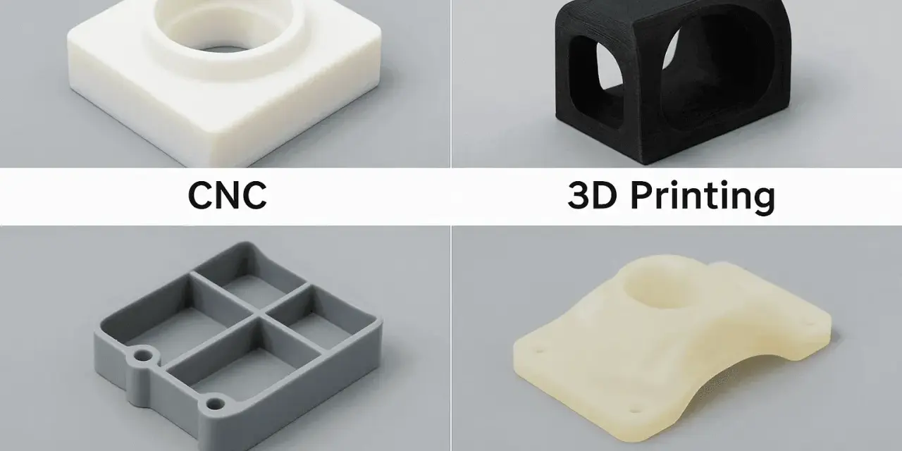
What machined parts do that printed parts cannot
In practical terms, I start with solid stock and remove material with mills, drills, lathes, and grinders until the part is left behind. CNC, short for computer numerical control, means the machine follows programmed toolpaths rather than being guided by hand. That matters because the process is very good at reproducing crisp geometry, real material properties, and functional surfaces without waiting for a tool to be built first.
For prototype work, that is the important distinction. A machined housing, bracket, bushing, or cover is not just a visual mockup. It is a test piece that can be assembled, torqued, sealed, loaded, and measured. If the prototype passes, I know much more about the design than I would from a shape-only model.
In my experience, the process pays off fastest when the part has one or more of these traits: a critical fit, a real load, a surface that mates to another component, or a material requirement that printing cannot reproduce cleanly. That sets up the next question: why this route still earns its place when additive options are easier to start.
Why it still makes sense for plastic prototypes
Plastic prototype work is where the choice becomes especially interesting. If I need a part to behave like the eventual production version, machining often gives me the closest answer without forcing me into tooling too early. A common starting tolerance for prototype CNC work is around ±0.005 in (0.13 mm), but I treat that as a baseline, not a promise. Thin walls, long spans, and heat-sensitive plastics can push the real window wider.
The other advantage is clarity. A machined prototype tells me whether a tolerance stack actually closes, whether a boss survives repeated assembly, and whether a sealing face is truly flat enough to trust. That is much harder to judge from a print that has different shrink behavior, layer structure, or surface texture.
| Option | What it gives you | Where it falls short | Best prototype use |
|---|---|---|---|
| Machined part | Real material, strong dimensional control, good surface quality | Higher setup effort, internal shapes are limited by tool access | Functional testing, fit checks, sealing surfaces, threaded features |
| 3D-printed part | Fast iteration, complex internal geometry, low setup burden | Material behavior and finish can differ from the final part | Form studies, early concept checks, complex passages |
| Molded part | Production-like economics at scale, repeatability, final-material workflow | Tooling cost and lead time are high upfront | Stable designs, higher volumes, launch-ready validation |
What I usually tell teams is simple: if the part’s value lives in accuracy, fit, and material behavior, machining is often the right prototype path. If the value lives in geometry that a cutter cannot reach, printing wins. If the design is stable and volume is growing, tooling starts to make sense. The decision is less ideological than people make it out to be, and that leads naturally into how the part actually gets from CAD to chips on the floor.
How the workflow moves from CAD to finished part
The cleanest prototype jobs follow a simple chain: design, plan, cut, inspect, refine. I like that because every step exposes risk before it becomes expensive. When the part is a plastic component, the workflow is usually more sensitive to fixturing, sharp tools, and heat than the same part in aluminum.
- Lock the critical dimensions first. I identify the datums, the sealing faces, the assembly holes, and any surface that other parts depend on. Datums are the reference faces used to measure the part consistently.
- Choose stock with enough margin. The starting block or sheet needs enough excess material for cleanup, facing, and clamping. Starving the part of stock is a common way to force bad setups.
- Build the toolpaths in CAM. CAM, or computer-aided manufacturing, converts the CAD model into cutter movements. This is where tool diameter, stepdown, and finishing strategy get decided.
- Simulate the cut and check collisions. A good simulation catches tool crashes, leftover stock, and awkward access before a real machine touches the part.
- Plan the fixturing. Fixturing is how the workpiece is held during cutting. If I need three repositionings to finish a simple plastic part, I already know the budget is going the wrong way.
- Deburr, inspect, and finish. The final part often needs edge break, cleaning, and a first-article inspection. First-article inspection is the measured check of the first completed part before the run continues.
When the geometry is straightforward, this can move quickly. For a simple plastic bracket or enclosure half, the work may stay within a few days once the queue is clear. Complex multi-setup parts naturally take longer. The key point is that the timeline is driven less by the act of cutting and more by setup quality, access, and how many times the part has to be repositioned. That is why material choice matters so much.
Which plastics machine well and which ones fight back
For plastics, I do not just ask, “Can this be cut?” I ask whether it will cut cleanly, hold shape, and still behave like the final product. Some grades are forgiving. Others punish dull tooling, poor clamping, or thermal abuse.
| Material | Why I pick it | Watch out for |
|---|---|---|
| ABS | Easy to machine, decent toughness, good for housings and fit checks | Heat buildup can smear edges; not a great choice for high-temperature service |
| Acetal (POM / Delrin) | Stable dimensions, low friction, clean edges, useful for moving interfaces | Can creep under poor clamping and is slippery enough to shift if fixturing is weak |
| Nylon | Tough, impact-resistant, good for clips and functional brackets | Moisture absorption can change size and feel over time |
| Polycarbonate | Strong and impact-resistant, useful when clarity and toughness matter | Can stress crack if the tooling is dull or the cut is too aggressive |
| Acrylic | Good for optical and display parts | Chips easily and rewards very careful feeds and sharp tools |
| PEEK | High-temperature, high-performance prototypes | Expensive, demanding on tools, and not forgiving if the process is rushed |
One point I always stress with plastics is that the material does not just define strength; it changes the whole machining behavior. Moisture, internal stress, heat, and cutter sharpness all matter more than many teams expect. If the production part will eventually be molded, I often try to prototype in the same resin family or as close to it as possible. That gives a better read on stiffness, creep, and assembly feel, and it leads straight into the design rules that save the most money.
The design rules that save the most money
The fastest way to turn a manageable part into an expensive one is to ignore how cutting tools actually work. I do not need every feature to be optimized, but I do need the part to be honest about what the machine can reach and hold.
Keep walls and ribs realistic
Very thin plastic walls are risky because they flex during cutting and can warp after the clamp comes off. As a practical starting point, I usually aim for about 1.5 mm or more on small plastic features unless the design has a strong reason to go thinner. If the wall is thinner than that, I want a clear explanation of why it has to be.
Design corners around the cutter
Sharp internal corners do not survive milling the way they survive in CAD. The smallest internal radius is governed by cutter size, so any pocket, slot, or recess should be drawn with that in mind. If a mating part needs a crisp edge, I usually ask whether the design can be changed to accept a radiused corner instead of forcing a tiny tool and a slower, less stable operation.
Spend tolerance only where the assembly needs it
I see a lot of prototype drawings with tight tolerances everywhere, and that is usually a mistake. Reserve the tight numbers for bores, sealing faces, datum features, and alignment points. Let non-critical cosmetic edges breathe. A drawing that tries to control everything often ends up controlling nothing well.
Plan the fixturing before you finalize the geometry
Good fixturing is quiet; bad fixturing shows up as scratches, distortion, and unnecessary setups. If a part cannot be clamped without crushing it, I redesign the part or the operation. That is especially important for soft plastics, thin shells, and long slender pieces.
Read Also: Small-Batch Plastic Manufacturing - Choose Your Best Process
Use inserts when the part will be assembled more than once
Repeated threading into plastic is fine for a demo and annoying in real use. For anything that will be opened, closed, or serviced repeatedly, I prefer heat-set or press-in inserts. They give the prototype a more production-like feel and protect the part from early wear.
Once these rules are in place, the remaining decision is not about geometry alone. It is about which manufacturing path best matches the goal of the prototype, and that is where a more direct comparison helps.
When machining beats printing and when it does not
I usually divide prototype choices by the kind of information the part must give me. If I need to know whether the design functions, machining is often the best answer. If I need to know whether the form looks right or the internal geometry is impossible to cut, printing may be smarter. If I need production economics, molding eventually takes over.
| If you need to prove | Best move | Why |
|---|---|---|
| Fit, alignment, sealing, torque, or load | Machine the part | You get real material response and more trustworthy interfaces |
| Complex internal channels or organic shapes | Print the part | A cutter cannot always reach the geometry without awkward compromises |
| A short bridge run before tooling | Machine it | You can validate the design in a real material before paying for a mold |
| Hundreds or thousands of stable parts | Move toward molding | Tooling cost starts to amortize across volume |
| One body with one critical interface | Use a hybrid approach | Print the rough form, machine the interface that actually matters |
That hybrid option is underrated. I have seen teams waste weeks trying to force one process to do everything. Often the smarter move is to let each process do its best job: print the complex shell, machine the datum surface, and assemble the two. That kind of pragmatism is usually what separates a decent prototype from one that actually informs production.
The checklist I use before I release the drawing
Before I send a plastic part out for machining, I run a short checklist. It is simple, but it catches most of the expensive mistakes before they become real chips.
- Are the critical dimensions actually marked as critical, or did I accidentally tighten the whole drawing?
- Do the walls, ribs, and bosses have enough material to survive machining and later assembly?
- Are the internal corners sized for cutter access instead of drawn like perfect CAD geometry?
- Have I chosen the right plastic for the test, not just the cheapest plastic on the material list?
- Is the part easy to fixture, inspect, and deburr without damaging cosmetic areas?
- Am I trying to machine a feature that should really be printed or molded instead?
If I answer those questions honestly, the prototype usually comes back useful the first time. That is the real strength of material-removal work: it gives me a part that behaves like a part, not just an idea with dimensions on it. When I use it well, I get faster decisions, cleaner design changes, and a much better path from early concept to production-ready plastic.